Profibus Installation Manual
12
4 Single and Dual Data Highway Configurations
4.1 Profibus Data Highway
The rules governing the installation and connection of a
Profibus DP highway should be observed at all times to
produce a successful installation. The highway does not allow
power to be transferred and the Profibus module is powered
from the actuator itself. The module can only report data
when the actuator is powered up.
PLC
+5V
0V
Probus DP Highway Screened cable
+5V
0V
Terminator
T
T
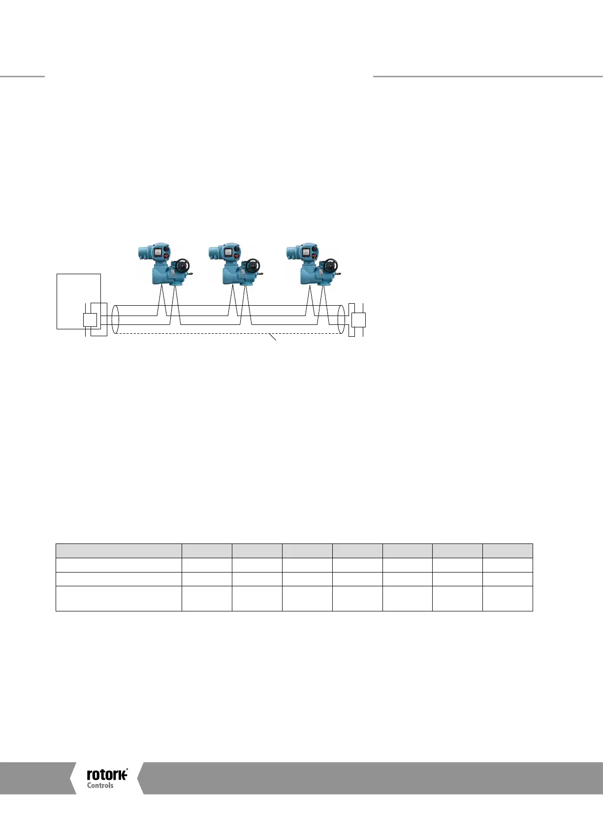
Fig. 5: Typical Profibus DP Data Highway
The data highway must be terminated with a proper active
termination network at each end of a segment. To ensure
successful operation the highway itself should not use tapped
spur or stub connections. The connection should be made
in and out of each actuator in a daisy chain arrangement
on separate terminals to eliminate any internal cabling stubs
inside the actuator. The length of the highway and number
of devices connected will vary from project to project. The
standard permits up to 32 devices to be connected on a
section, though one of these will be the PLC. If more devices
are needed (up to the maximum addressable of 126) then
repeaters may be added as required. Up to 9 repeaters can
be used on a single highway provided no more than 4 are
between any two devices.
Data Rate (Baud) 9600 19200 45.45k 93.75k 187.5k 500k 1.5M
Maximum Segment Length
1.2 km 1.2 km 1.2 km 1.2 km 1000m 400m 200m
Maximum Highway Length
10 km 10 km 10 km 10 km 10 km 4 km 2 km
Max number of actuators/
segment
31
1
31
1
31
1
31
1
31
1
31
1
31
1
Note¹ – The PLC or Repeater module will be one device. Max 32 devices/segment
Since the data passes over a single 2-wire cable there are
periods between messages when no devices are actively
driving the lines. In order to ensure that data continues to
flow correctly after these periods it is advisable to ensure the
lines are biased to suitable voltage levels during the time the
line is idle. The PFU contains active termination circuits that
ensure suitable levels are maintained on the line even with no
device transmitting.
Single and Dual Data Highway Configurations
A4US
US
A4
US A4
US
A4
 Loading...


