Keeping the World Flowing
37
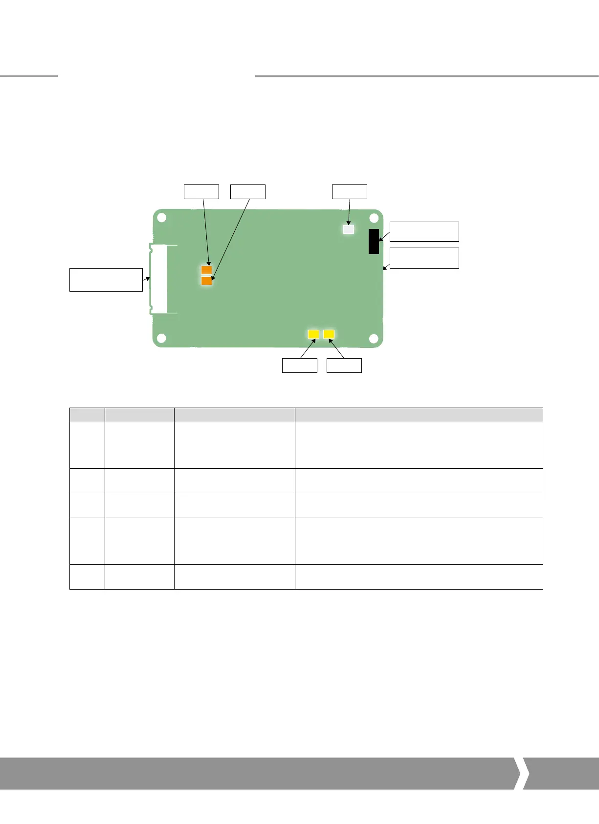
6.6 Dual Channel Indication LEDs
If the actuator cover is opened there are several LEDs on the
circuit board that are used to indicate communication activity.
These indicate both the communication between the Profibus
highway and the card and the communication within the
card’s two main processors.
LED 1 LED 2
LED 3
LED 4
LED 5
SK 1,
CAN Connection
SK 2 (on reverse),
CAN Connection
SK 3,
Field Connections
Fig. 22: Dual Channel Profibus card LED positions
LED Description State Function
1
Orange LED
(Channel 1)
Flash (variable speed)
Flash’s when receiving Profibus messages on channel one.
This LED flashes at the rate of the incoming messages, so
faster baud rates will cause a faster flash (will appear dimmer
at faster speeds).
2
Green LED Slow flash
Indicates communication and power between the Profibus card
and the actuator main board.
3
Yellow LED
(Channel 1)
Solid on Indicates Profibus cyclic DPV0 communications on channel 1.
4
Orange LED
(Channel 2)
Flash (variable speed)
Flash’s when receiving Profibus messages on channel two.
This LED flashes at the rate of the incoming messages, so
faster baud rates will cause a faster flash (will appear dimmer
at faster speeds).
5
Yellow LED
(Channel 2)
Solid on Indicates Profibus cyclic DPV0 communications on channel 2.
For SK functions please see the table in section 3.1.
Profibus DP Communication
A4 US
US
A4
US
A4
A4 US
 Loading...


