Keeping the World Flowing
41
7.1.1 Limited Range Position Minimum and Maximum
(Parameter 1 and 2)
These parameter registers are used to define the positions
in the range of valve travel that will be reported as 0 to
100% if the whole travel from the closed position to the
open position is not used. In addition the position demand
set-point output value will also be modified to follow this
limited range.
It is possible to make the position data reported and the
position controller relate to a reduced span of actual valve
travel. In this mode the position data relates to the reduced
portion of the valve stroke. This is sometimes used where the
valve is required to have a 0% position (or 100% position)
that is not the same as the fully closed position (or fully open
position). These parameters define the actual limited range
of valve travel that will be used for the position reporting and
control by the positioner.
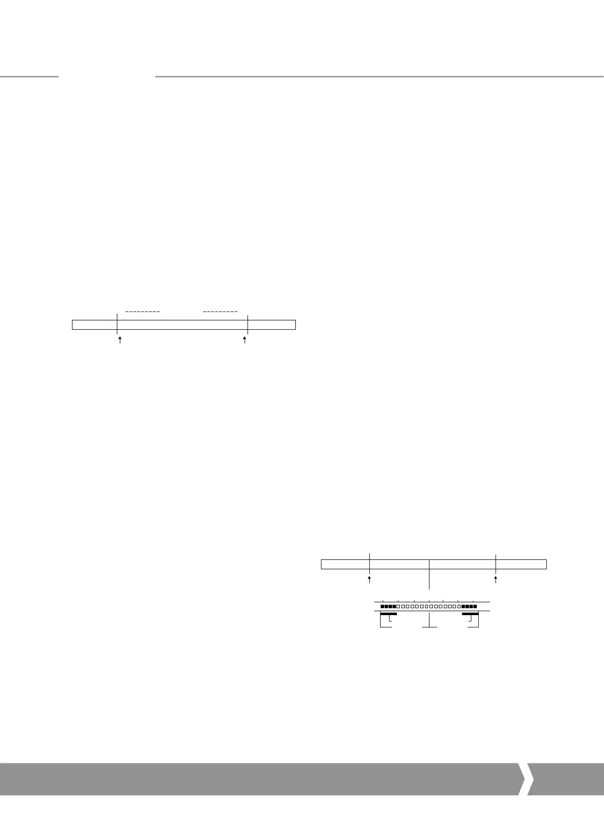
Valve Stroke
CLOSED OPEN
Position Minimum Setting Position MaximumSetting
0% 100%Reported Position
Fig. 24: Limited Range Position Control and Reporting
Note that the digital open and close commands will still make
the valve travel over its full stroke. The special case analogue
commands of 0% and 100% that would otherwise cause the
actuator to travel to the limit switch or torque off positions
are inhibited if values other than 0 and 100 are set in these
parameters (limited range position parameters).
The values inserted relate to the maximum total valve travel
between closed and open and represent the point in the full
stroke which will now be used for the limited stroke 0 and
100 values.
Parameters
7.1.2 Deadband and Hysteresis (Parameter 3 and 4)
When using position control by sending a value to the
Actuator Position DV set-point there are a number of
parameter registers used to tune the position controller and
reduce the possibility of damage to the actuator. These two
registers are set to prevent hunting around the set-point due
to high inertia of the valve. They will require adjustment for
each specific application. In addition the Motion Inhibit Timer
is used to ensure the actuator does not carry out an excessive
number of starts in a given period.
Deadband
The control used for the positioner is proportional only.
The PFU will run the actuator to the desired position and
then it stops. As the actuator and valve combination have
some inertia there is a possibility that the desired position
may be overrun and the positioner will then reverse the
direction of travel to make the valve adopt the desired
position. This overshoot and return may continue for a
number of cycles and is known as hunting. The valve and
actuator combination will hunt around the set-point if
the inertia is high. To prevent this from happening there
is a Deadband setting whereby once the actuator enters
the deadband the motor will be stopped. For example a
5% deadband will cause the motor to be stopped once
the actual position is within 5% of the desired position.
The inertia will then bring the actual position nearer the
desired position.
The deadband is the allowable error around the set point.
Hysteresis
In addition to the deadband a second setting, hysteresis,
further refines the performance of the position controller.
The positioner will run the actuator towards the setpoint
DV until the actual position is within the deadband minus
the hysteresis setting. This has the effect of instructing the
actuator to stop when it is nearer the DV. The actuator
will not restart unless it overshoots and runs outside the
deadband or a new command places the new desired
position outside the deadband.
Fig. 25: Deadband and Hysteresis settings
The Hysteresis is the amount of movement inside the
deadband permitted before the motor stops.
Valve Stroke
CLOSED OPEN
Position Minimum Setting Position MaximumSetting
0%
47% 48% 49% 50% 51% 52% 53%
100%
Setpoint DV = 50%
Position MV = 50%
Hysterisis
Hysterisis = 1%
Hysterisis
A4 US
US
A4
US
A4
A4 US
 Loading...


