Keeping the World Flowing
45
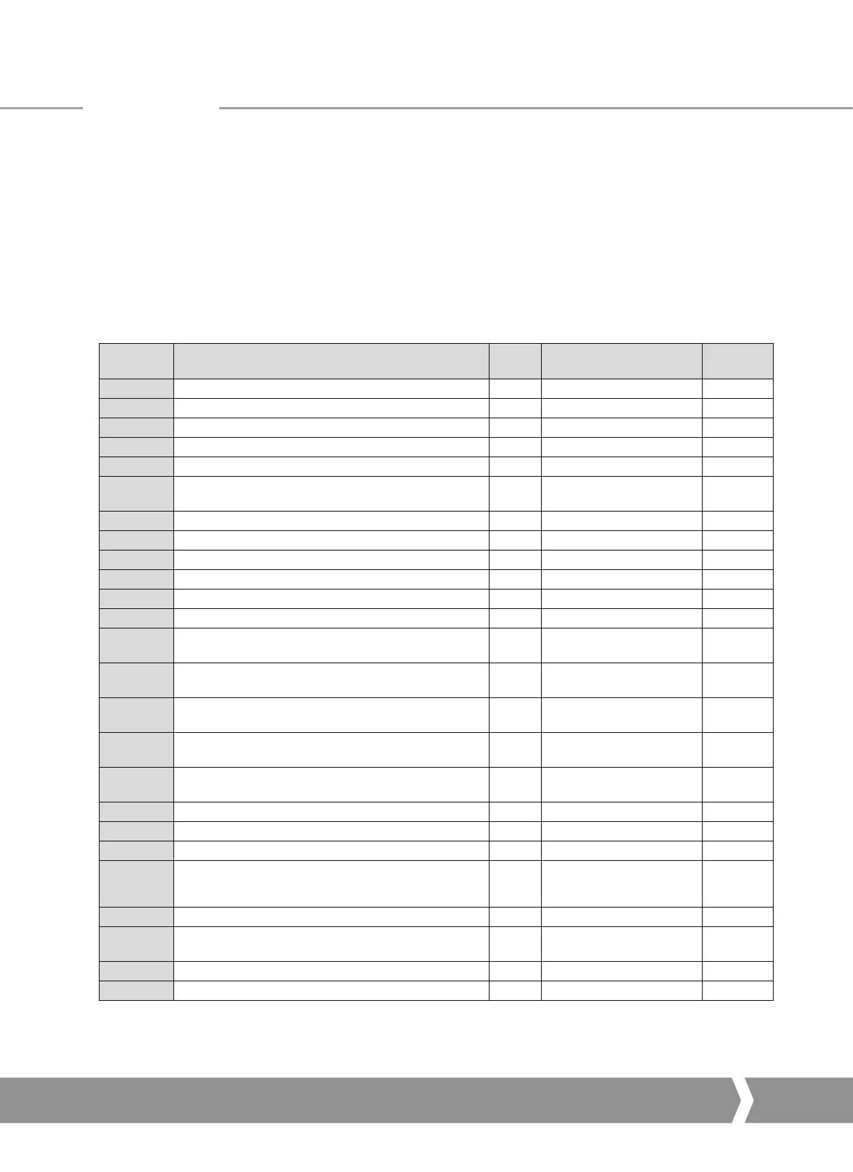
Parameter
No.
Data
Read /
Write
Value / Range
Default
Value
20 Actuator Tag data R/W 12 byte 0
21 Actuator software version R 12 byte e.g. V013
22 Profibus interface software version R 12 byte e.g. V101
23 Reserved
24 Field Interface type R 00 to FF 02
25 Permit GSD Parameterisation R/W
1 = Permit GSD
0 = Lock out GSD
1
26 Actuator digital control R/W 0000 to FFFF 0
27 Actuator position control R/W 0000 to FFFF 0
28 Reserved
29 Additional Control Flags R/W 0000 to FFFF 0
30 Input data IDATA1/2 R 0000 to FFFF 0000
31 Input data IDATA3/4 R 0000 to FFFF 0000
32 Torque feedback2 R
0-120%,
0000 to 0078 hex
0
33 Position feedback3 R
0-100.0%,
0000 to 03E8 hex
0
34 Temperature R
-32767 to +32767
o
C
0000 to FFFF
0
35 Analogue Input Calibration4 R/W
1 = Calibrate High Signal
2 = Calibrate Low Signal
0
36 Analogue Input4 R
0 - 100.0%,
0000 to 03E8
0
37 Reserved
38 Reserved
39 Reserved
401 Configure Data Exchange Data R
1-10,
1 to 000A hex
0
41- 67 Reserved
68 Parameterisation Date (8 ASCII character string dd/mm/yy) R/W
DD/MM/YY,
8 byte
0
69 Reserved
70-77 Reserved
7.2 Parameters viewed and set by DP-V1 Communication
The Profibus DP Module supports V1 acyclic communication
as well as V0 cyclic messages. These parameters can be
accessed in a number of ways including using standard
Profibus tools and the specialist device description files
associated with them.
•
FDT Field Device Tool, this utility requires a
DTM (Device Type Manager) file.
•
PDM Process Device Manager, this tool requires an
EDD (Electronic Device Description) file
The Profibus DP Module supports both these utilities. The
list of parameters that can be accessed by these tools is as
below. These tools will allow the actuator to be controlled
and monitored by the tools as they support the display
of the registers containing feedback status and output
commands. The size of the parameter is listed together with
the ability to Read (R) or Write (W) to the parameter using
one of these utilities.
For V1 read and writes the slot number is 0 for all parameters
and the index number is the parameter number shown in
the table.
Parameters
A4 US
US
A4
US
A4
A4 US
 Loading...


