Keeping the World Flowing
47
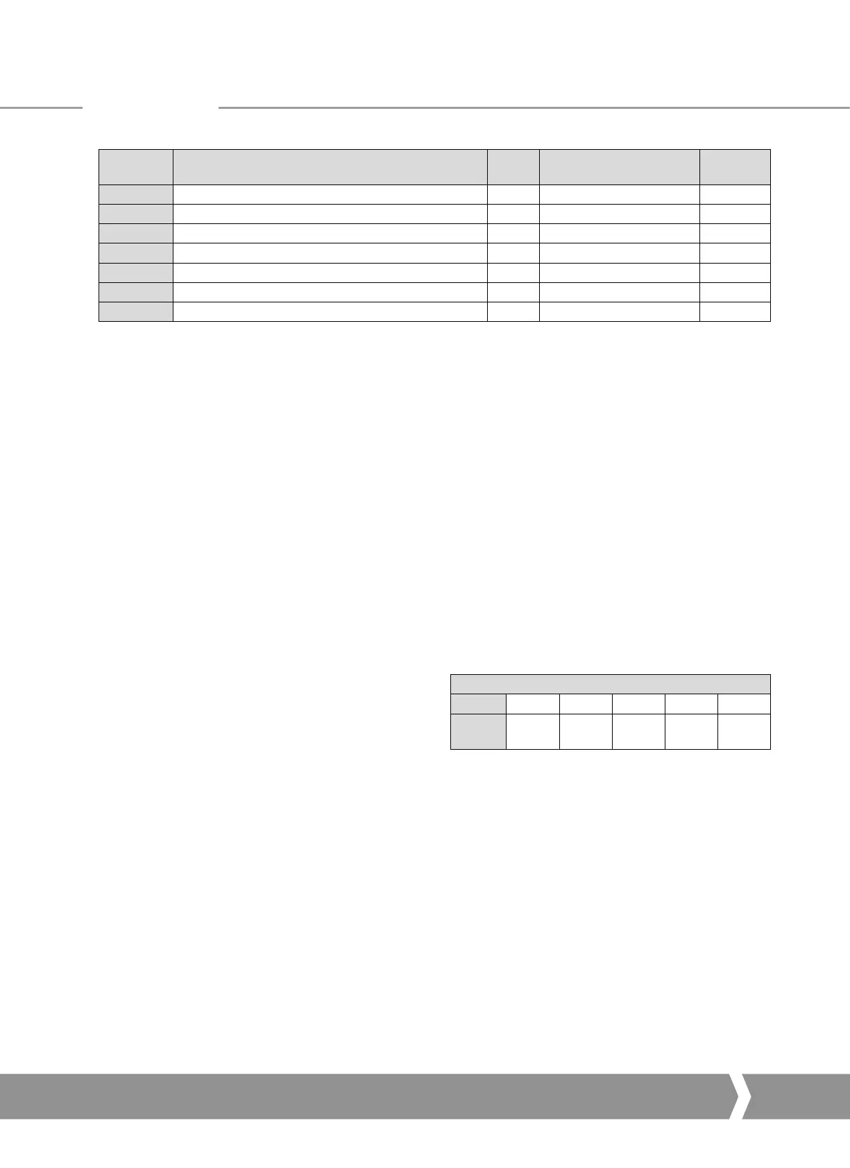
Parameter
No.
Data
Read /
Write
Value / Range
Default
Value
114 ID Power R 16 bytes ASCII -
115 ID Option1 R 16 bytes ASCII -
116 ID Option 2 R 16 bytes ASCII -
117 Reserved -
118 Reserved -
119 Manufacture notes R 48 bytes ASCII -
120 General Notes R/W 67 bytes ASCII -
Note
1
- Only readable by V1 comms on Simple Dual and
RedCom Dual modules.
Note
2
- Only on units with a DSM.
Note
3
- Only available on unites with a DSM or MSM with
optional potentiometer.
Note
4
- Requires extra option card.
7.2.1 Actuator Tag Data (Parameter 20)
This parameter allows the Profibus card to hold a tag name
for the actuator, up to 12 characters long.
7.2.2 Software Versions (Parameter 21 and 22)
Parameter 21 holds the Interface card software version in the
form VXXX and parameter 22 holds the Profibus network
interface card software version in the form VXXX.
7.2.3 Field Interface Type (Parameter 24)
This parameter reports the type of network interface card
fitted. It will read 02 for a Profibus card.
7.2.4 Permit GSD Parameterisation (Parameter 25)
If the Profibus card has been set up using FDT or PDM it
may be desirable to prevent any of parameters 1 to 19 from
being altered by the GSD file during normal start up or on a
power cycle. If the actuator is switched off, then back on, the
standard Profibus start up routine will impose the parameter
values set in the GSD file for the device.
This parameter allows the card to be set to ignore the GSD
parameterisation routine. If it is set to ‘1’ then the GSD
Parameterisation is permitted. The default value is 1.
7.2.5 Control Outputs (Parameter 26 to 29)
Parameter 26 allows the actuator to be controlled using the
same values as in the ACTCON register described in section
5.1.2. Parameter 27 (in conjunction with Parameter 26) allows
the actuator to be positioned using the same values as in the
POS_DV register, refer to section 5.1.3.
Parameter 29 allows the relay outputs to be controlled as
described in section 5.1.4
Parameter 29
Bit 4 - 15 3 2 1 0
Function
Reserved
DO-4
control
DO-3
control
DO-2
control
DO-1
control
7.2.6 Configure Data Exchange (Parameter 40)
The data to be exchanged during normal cyclic data exchange
is determined by the Configuration set during start-up of
communication between the PLC and the Profibus card.
In setting up the card from the PLC one of the 10 possible
Configuration will have been chosen – refer to section 5.4.
Parameter 40 shows which of the 10 possible configurations
has been chosen and allows the choice to be verified. It
cannot be changed except by the choice entered during the
configuration stage.
7.2.7 Parameterisation Date (Parameter 68)
This parameter can be set to contain information showing
the date when the card was set up. The format for the entry
should be DD/MM/YY. This parameter does not automatically
update and must be set manually.
Parameters
A4 US
US
A4
US
A4
A4 US
 Loading...


