Keeping the World Flowing
23
5 The Actuator Cyclic Data Signals
The Profibus DP Module allows the actuator to be controlled
by, and to report data to, a suitable host device using Profibus
DP protocol. This section explains the data signals that are
presented during cyclic V0 data exchange and their meaning
in relation to the actuator functionality. The register locations
used for the data exchange are given later in this manual.
This section also gives information on the other control inputs
available for moving the actuator.
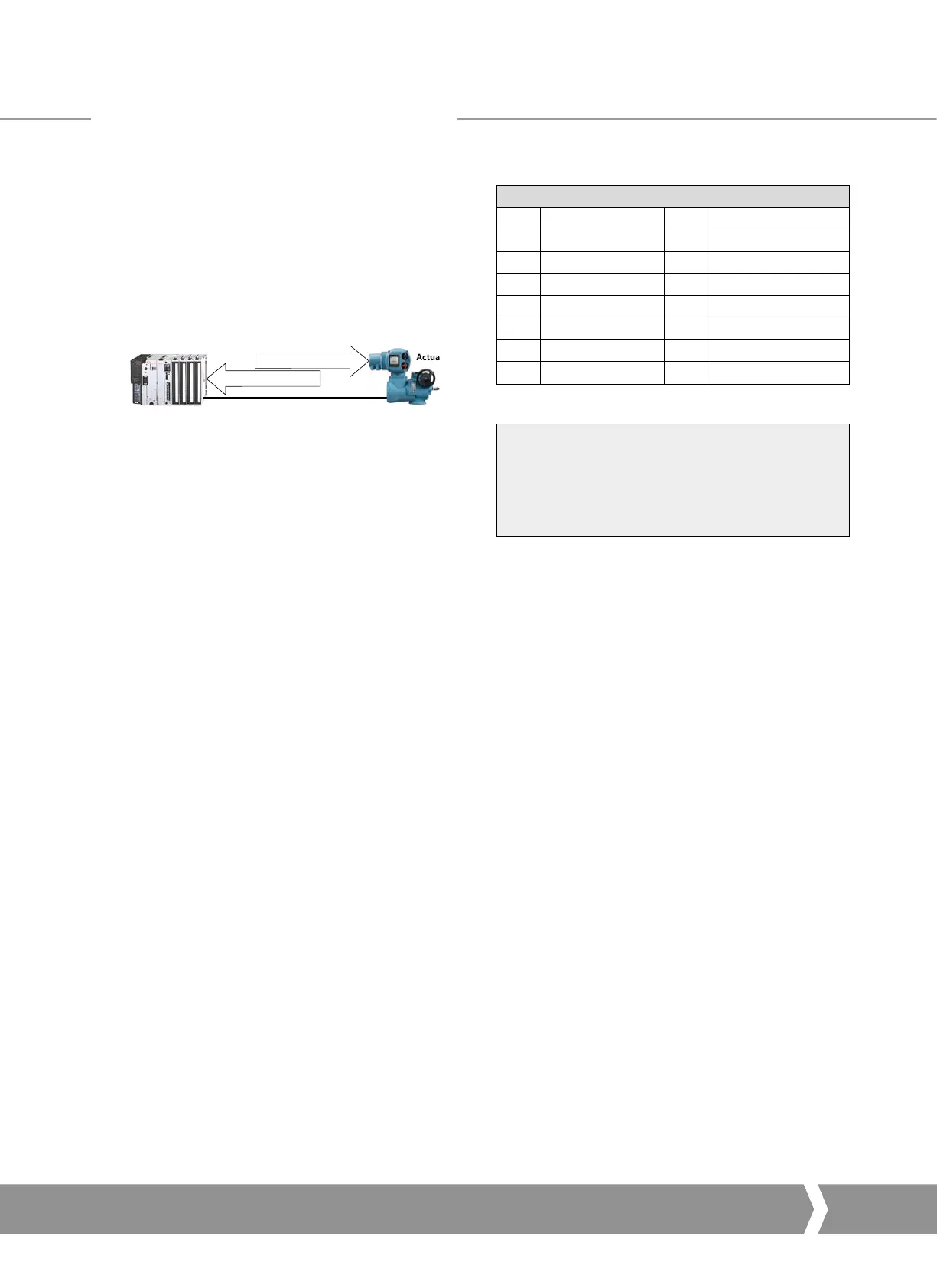
Probus DP (RS-485) Data Highway
PLC Actuator
Outputs - Commands
Inputs- Feedback
Fig. 17: Input and Output Data Direction
•
Outputs are defined as signals originating at the PLC and
operating the actuator controls.
•
Inputs are defined as signals originating at the actuator
and fed back to the PLC over the Profibus network.
Cyclic Data Exchange
Output Registers Input Registers
1
ACTCON 1 IDATA2 / IDATA1
2
POS_DV 2 IDATA4 / IDATA3
3
O_STAT 3 TORQUE
1
4
RESERVED 4 POSITN
1
5 TEMPER
6 RESERVED
7 RESERVED
Note¹ : – Requires a DSM or an MSM with optional potentiometer.
The actual registers exchanged during normal
cyclic data exchange will depend on the
Configuration set for the card. Section 5.4
contains information on the Configuration
options available.
The Actuator Cyclic Data Signals
A4 US
US
A4
US
A4
A4 US
 Loading...


