Keeping the World Flowing
35
6.4 Dual Highway, Dual Channel – SR Mode
When using the Simple or RedCom Dual Channel card the
mode for communication has to be selected between SR
(System Redundancy) and FR (Flying Redundancy). This is
chosen during parameterisation by the GSD file values or by
using a parameterisation utility such as FDT or PDM.
Redundancy
The default setting for redundancy is SR mode
In SR mode there are two highways and a redundantly
configured PLC. The two channels on the card both use
the same address. One channel is in Primary mode whilst
the other is in Backup mode. The card is waiting for a
communication message on the channel that is in Primary
mode and the two channels will switch their mode whilst
searching for comms. There is no discrimination between
Channel 1 and Channel 2 to determine which is in Primary
mode. The two channels will both try to adopt Primary mode.
When using either the Simple or the RedCom dual channel
card in SR mode the following must be set up:
Address
The two channels share the same common address. The
address can be set using the Accent software directly with
the actuator (free from www.Rotork.com) or using the
setting tool. The address can also be set over the highway
using a Class 2 master.
Baud Rate
This is selected by the PLC, both channels adopt the same
baud rate.
Slave Configuration
One of the 10 configurations for the slave must be chosen.
Both channels will use the same configuration setting.
Configuration can only be carried out on the Primary
channel.
Basic Parameterisation
The basic parameters such as deadband and motion inhibit
time can be set using either the GSD file or a suitable PDM
or FDT utility. The default settings will be suitable for most
systems. Both channels will adopt the same settings.
Parameterisation can only be carried out on the
Primary channel.
IDATA4 Bit 5 indicates the channel status and will show if
the channel in communication is the Primary or Backup.
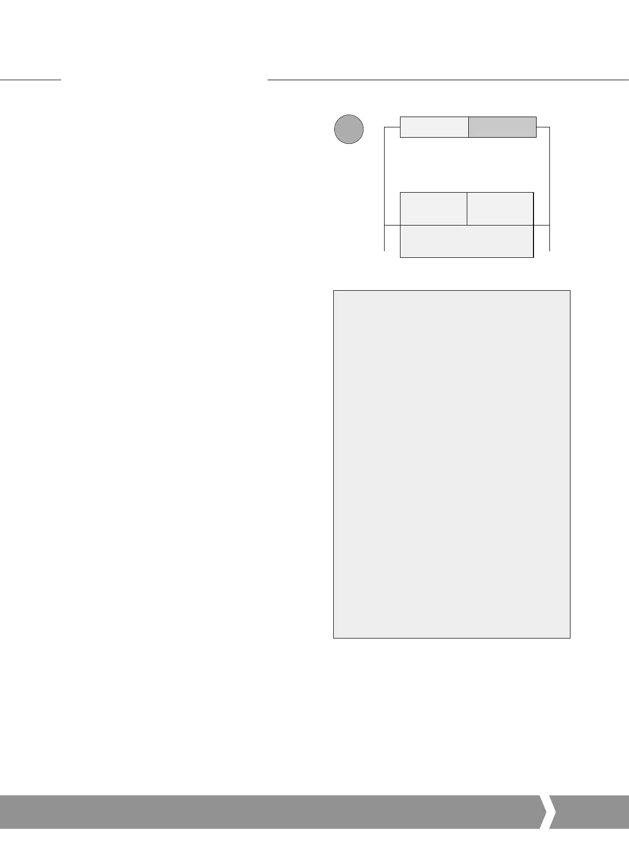
Primary
address # = n
Backup
address # = n
SR
Master PLC
Highway 1 Highway 2
Standby PLC
Probus Card
Fig. 20: System Redundancy – Two highway redundancy
SR Mode -
•
Both channels have the same slave address.
•
When the card is powered ‘on’ Channel 1
will be the Primary channel. After power up
the card will seek a master to communicate
with by alternating the channel 1 and 2
between Primary and Secondary mode. The
switch over time increases with each change
to a maximum of 32 seconds. The card will
continue to switch channels using a 32 second
switch over time until one channel receives
PLC messages.
•
It may be necessary for the PLC to wait until
the correct channel is in Primary mode before
communication is started.
•
If the Primary channel fails, the Backup will
automatically adopt Primary status and wait
for messages from the second master.
•
The Backup channel can be used for
exchanging data but any commands to move
the actuator directed to the backup channel
will be ignored.
•
If a configuration message is sent to the
Backup channel that is different to the one
sent to the Primary it will be accepted, but not
carried out.
Profibus DP Communication
A4 US
US
A4
US
A4
A4 US
 Loading...


