Profibus Installation Manual
40
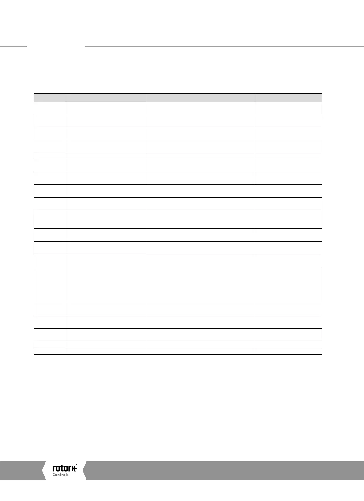
The parameters that may be set by the GSD exchange or V1
comms (Where V1 read and write slot number is 0 for all
parameters and the index number is the parameter number
shown in the table) are:
Param. No. Description Value/Range Default Value
1 Limited Range Position Minimum
0-100%
0000 – 0064 hex
0%
0000 hex
2 Limited Range Position Maximum
0-100%
0000 – 0064 hex
100%
0064 hex
3 Deadband1
0.0– 25.5%
0000 – 00FF hex
5.0%
0032 hex
4 Hysteresis1
0.0– 25.5%
0000 – 00FF hex
2.0%
0014 hex
5 Reserved N/A N/A
6 Motion Inhibit Time
0 – 255 sec
0000 – 00FF hex
5 sec
0005 hex
7 Manual Movement Travel
0 – 100%
0000 – 0064 hex
10%
000A hex
8 Valve Jammed Time
0 – 255 sec
0000 – 00FF hex
5 sec
0005 hex
9 Watchdog Timeout
0 – 255 sec
0000 – 00FF hex
10 sec
000A hex
10 Action on Loss of Comms
0 = Nothing (No Action)
1 = Open
3 = Close
5 = Stop
7 = Position
Any other value = Off
0 = Nothing (0000 hex)
11 Comms Lost Position
0 – 100%
0000 – 0064 hex
0% 0000 hex
12 Comms Fault Timer
0 – 255 sec
0000 – 00FF hex
255 sec 00FF
13 Aux Input Mask
0 – 255
0000 – 00FF hex
15 00FF hex
14
ESD DI4/Net Disable and Data logger
disable
DI-4 is ESD = 0 or 2
DI-4 is Net Disable = 1 or 3
Data Logger is enabled = 0 or 1
Data Logger is disabled = 2 or 4
(Bit 0 = EDS/Net disable
Bit 1 = data logger en/disable)
ESD and Data Logger enabled 0
0000 hex
15
Redundancy FR/SR mode and Simple/
RedCom mode
Bit 0 : SR mode = 0, FR mode = 1
Bit 1 : Simple = 0, RedCom = 1
02
0000 hex
16 Part Stroke position
1 – 99%
0001 – 0063 hex
90
005A
17 Part Stroke Limit and timeout
Bit 15 is 0 for close limit and 1 for open limit.
Bits 0-14 are time values in seconds for timeout
Open and 300 secs 812C hex
18 Actuator Type 0 – Unknown (default), 23 – Rotork 0
19 Reserved N/A N/A
Note - On Redcom Dual Channel cards the default is 2 (0002 hex)
These parameters set up the response the actuator will make
to various control and network actions. There are three GSD
files, one for a single channel card, one for a simple dual
channel and one for a RedCom dual channel card. They all
contain the same number of parameter settings.
•
Single Channel Card GSD file RTRK0845
•
Simple Dual Channel Card GSD file RTRC0845
•
RedCom Dual Channel Card GSD file RTRR0845
Parameters
A4US
US
A4
US A4
US
A4
 Loading...


