A4US
US
A4
US A4
US
A4
A4 US
US
A4
US
A4
A4 US
IQ3 Full Configuration Manual – Section: Settings 23
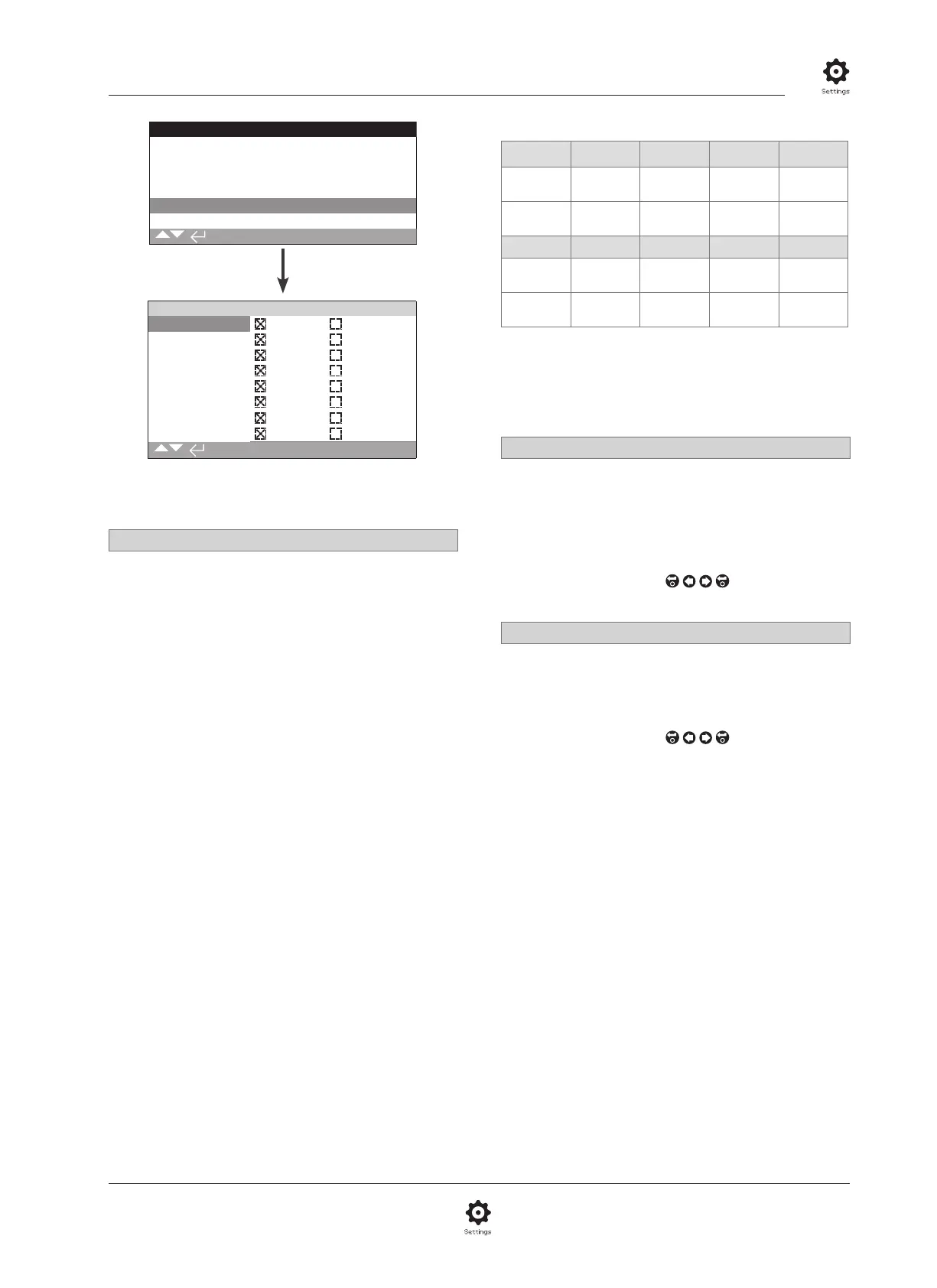
2.3.2-5 Control – Remote – Auxiliary Mask
Remote Control
Hardwired
Control Source
Partial Stroke
Positioning
Auxiliary Mask
Analogue
Auxiliary Mask
Auxiliary 1 Dig In Open
Contact 1 N/O N/C
Auxiliary 2 Dig In Close
Contact 2 N/O N/C
Auxiliary 3 Dig In Maint.
Contact 3 N/O N/C
Auxiliary 4 Dig In ESD
Contact 4
N/O N/C
1/8
The Auxiliary Mask settings page is shown above with
default settings visible.
Introduction
When a Network option is fitted (Pakscan/Profibus/Modbus/
Foundation Fieldbus or HART) a facility to accept 4 Auxiliary
inputs is available. Auxiliary inputs can be set as supplementary
control for the actuator (open, close, stop/maintain or ESD) or
as digital indication inputs whose status is reported over the
option network. It is also possible to have a combination of both
supplementary remote control and digital inputs to provide, for
example, open and close control as well as a high and low tank
level alarm indication from external level transducers.
Auxiliary inputs are in addition to the standard control and
feedback features incorporated into a Network option. Auxiliary
inputs are connected to the standard Open, Close, Stop/maintain
and ESD inputs. Refer to wiring diagram.
NOTE: If an Analogue option and a Network option are
fitted and hardwired ESD control is required (Auxiliary 4 set to
ESD), ensure Auxiliary contact 4 setup is matched to the ESD
configuration when signal setting. Refer to 2.4.
The Auxiliary Mask page allows the user to setup the 4 Auxiliary
inputs as supplementary control, indication or a combination
of both. Each Auxiliary input can be set for the type of contact
connected. Refer to Auxiliary input setup.
Auxiliary Input Setup
Input Auxiliary 1 Auxiliary 2 Auxiliary 3 Auxiliary 4
Control Open Close
Stop/
Maintain
ESD
Indication Dig Dig Dig Dig
Contact Type Contact 1 Contact 2 Contact 3 Contact 4
Normally
Open
N/O N/O N/O N/O
Normally
Closed
N/C N/C N/C N/C
A normally open contact is considered to be in the active
state when the contact is closed. A normally closed contact is
considered to be in the active state when the contact is open.
Using Auxiliary 1 and Contact 1 as an example:
1/8 Auxiliary 1
Refer to Auxiliary input setup.
Dig in (default) – Network option will report digital input
status: 1 or 0
Open – Hardwired open command signal is required. Use
Auxiliary 2 to 4 for close, stop/maintain and ESD.
To change the settings use,
. The checkbox will
indicate the set Auxiliary 1 input function.
2/8 Contact 1
Refer to Auxiliary input setup.
N/O (default) – A normally open contact is used to derive input.
N/C – A normally closed contact is used to derive input.
To change the settings use,
. The checkbox will
indicate the set Contact 1 input type.