A4US
US
A4
US A4
US
A4
A4 US
US
A4
US
A4
A4 US
IQ3 Full Configuration Manual – Section: Settings 29
2.3.2-10 Control – Remote – Modbus
Remote Control
Analogue
Pakscan
Profibus
HART
Modbus
Extra I/O
Modbus
Address 247
Termination On Off
Baud Rate 9600
Parity/Stop None/1 stop
Second Address 247
Control CH1 Ctrl Ch2 Ctrl
1/6
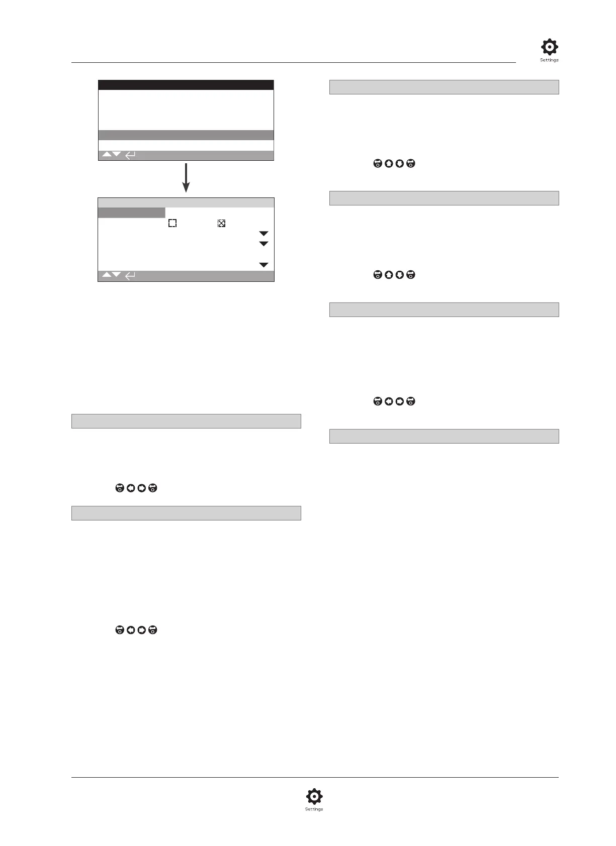
The Modbus Control option settings page is shown above
with its default settings. Modbus is a control option and is
available in single or dual channel versions, refer to wiring
diagram.
Depending on the Modbus control scheme, other related settings
may be required, refer also to:
2.3.2-4 Positioning
2.3.2-5 Auxiliary Mask
1/6 Address
The Modbus option must be allocated a unique address in the
system to which it is attached. Changes made to this parameter
will take effect immediately. The address range is 1 – 247
(default 247).
To change,
. The set address will be indicated.
2/6 Termination
Modbus networks require termination resistors at each end
of the highway. The Modbus option has a passive (120 Ohm)
termination resistor (2 for dual) built in, which can be switched in
or out of the circuit.
Off (default) - Termination resistor(s) switched out.
On – Termination resistor(s) switched in. In a dual channel
Modbus option, when On is selected the termination resistors
will be switched in for both channels.
To change,
. The checkbox will indicate the set
termination mode.
3/6 Baud Rate
The Modbus option must be set to the RS485 highway
baud rate. Changes made to this parameter will take effect
immediately. The baud rates selectable using the drop down box
are 110, 300, 600, 1200, 2400, 4800, 9600, 19200, 38400,
57600, 115200.
To change,
. The drop down list will close and
the selected baud rate will be indicated.
4/6 Parity/Stop
Where Modbus parity bit detection is used, the module must
be set with the same parity settings as the host. The choices of
parity are None, Even, Odd. This item also allows selection for
the number of stop bits as 1 or 2. The drop down box requires
selection of the parity and stop bits together.
To change,
. The drop down list will close and
the selected parity and stop bit will be indicated.
5/6 Second Address
Used for dual Modbus option (redundant) only. Refer to wiring
diagram.
A dual Modbus card has 2 channels available for connection to
separate or the same highway(s). The second channel address
is set up with this setting. It may be identical or different to the
first channel depending on the requirement of the system.
To change,
. The set second address will be
indicated.
6/6 Control
Not editable. For dual Modbus option (redundant) Only.
Refer to wiring diagram.
Setting will indicate that control is available on both channels
1 and 2.