TROUBLESHOOTING—TROUBLESHOOTING WITH STATUS LEDS
52
TROUBLESHOOTING
TROUBLESHOOTING WITH STATUS LEDS
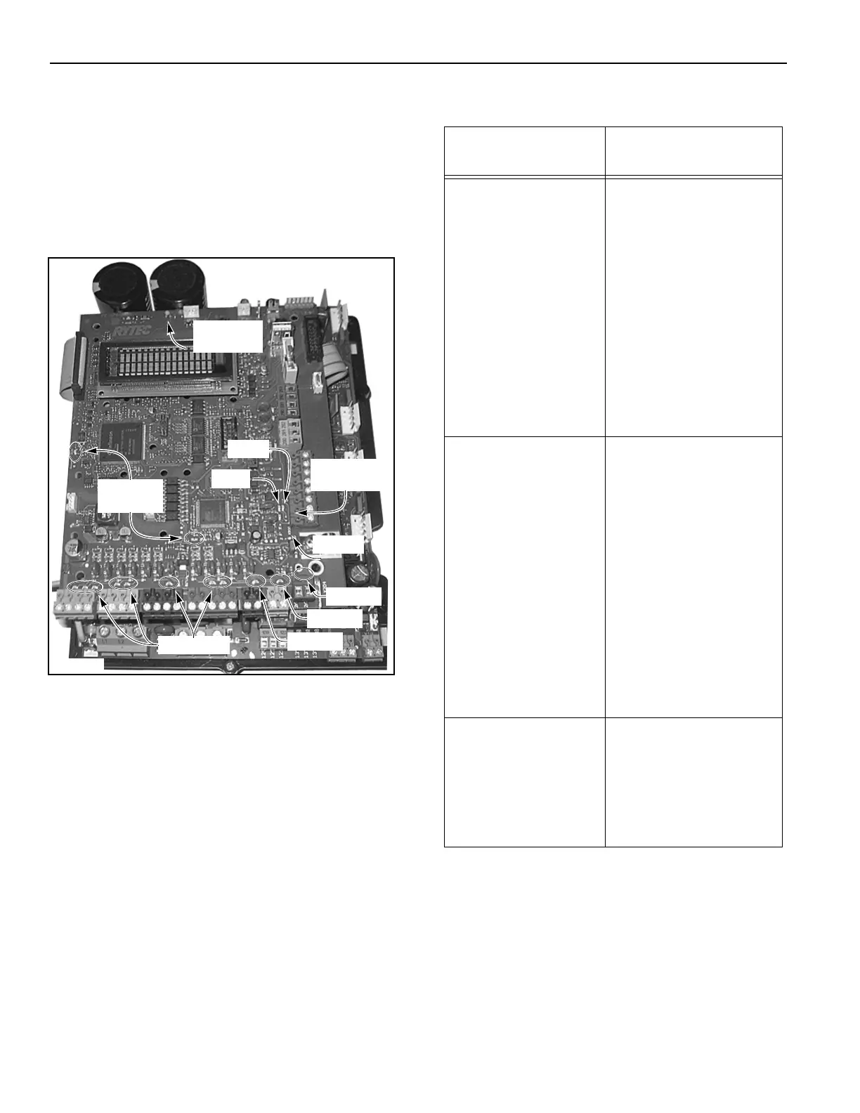
If a problem occurs with the control system or the door,
the controller is configured with various light-emitting
diodes (LEDs) that can be helpful when troubleshooting
the problem. The LEDs are grouped in various functions
and indicators as detailed in Figure 46. Table 26 below
details the interpretation of each group of LEDs.
Figure 46
Table 26
A5400016
Reversing
Edge LEDs
Input LEDs
Run LEDs
(Green)
Red
Green
E-Stop 3
E-Stop 2
E-Stop 1
Ajar LED
24V Short
LED
LED Group
Associated LED
Function
Emergency Stop
Chain LEDs
NOTE: Reference
Figure 46 for
LED Loca-
tion
1 = E-Stop 1
First External E-Stop
2 = E-Stop 2
Second External E-Stop
3 = E-Stop 3
Third External E-Stop
Note: LEDs 1, 2, and 3
must all be on for normal
operation.
Input LEDs
(LEDs on = contact
connection closed
LEDs off = contact
connection open)
4 = breakaway input
5 = front photo eyes
6 = rear photo eyes
7 = alternate action
activator
8 = auto-close activator 1
9 = auto-close activator 2
10 = auto-close
activator 2
11 = open
12 = close
13 = stop
14 = is a programmable
input
15 = is a programmable
input
Reversing Edge
LEDs (Green and red)
Normal operation = red is
OFF and green is ON.
0 ohms (short) = red and
green are both OFF.
Infinite ohms (open) =
both red and green LEDs
are ON.