SYSTEM PARAMETERS—CLOCK INPUT SELECTION
39
CLOCK INPUT SELECTION
The System 4 controller has four clock input channels
(A, B, C, and D) that can be used to perform special
timed events. For instance, these inputs can be used to
lock a door during specific hours or days of the week, or
open the door during break times or other scheduled
times during the day. The four channels allow the poten-
tial of four events to occur each day. If you are interested
in setting the clock for a particular event, contact Rytec
Customer Support at 800-628-1909. Please have the
door serial number and the specific scenario you would
like to perform.
Table 10
SWITCHING CLOCK PROGRAMS
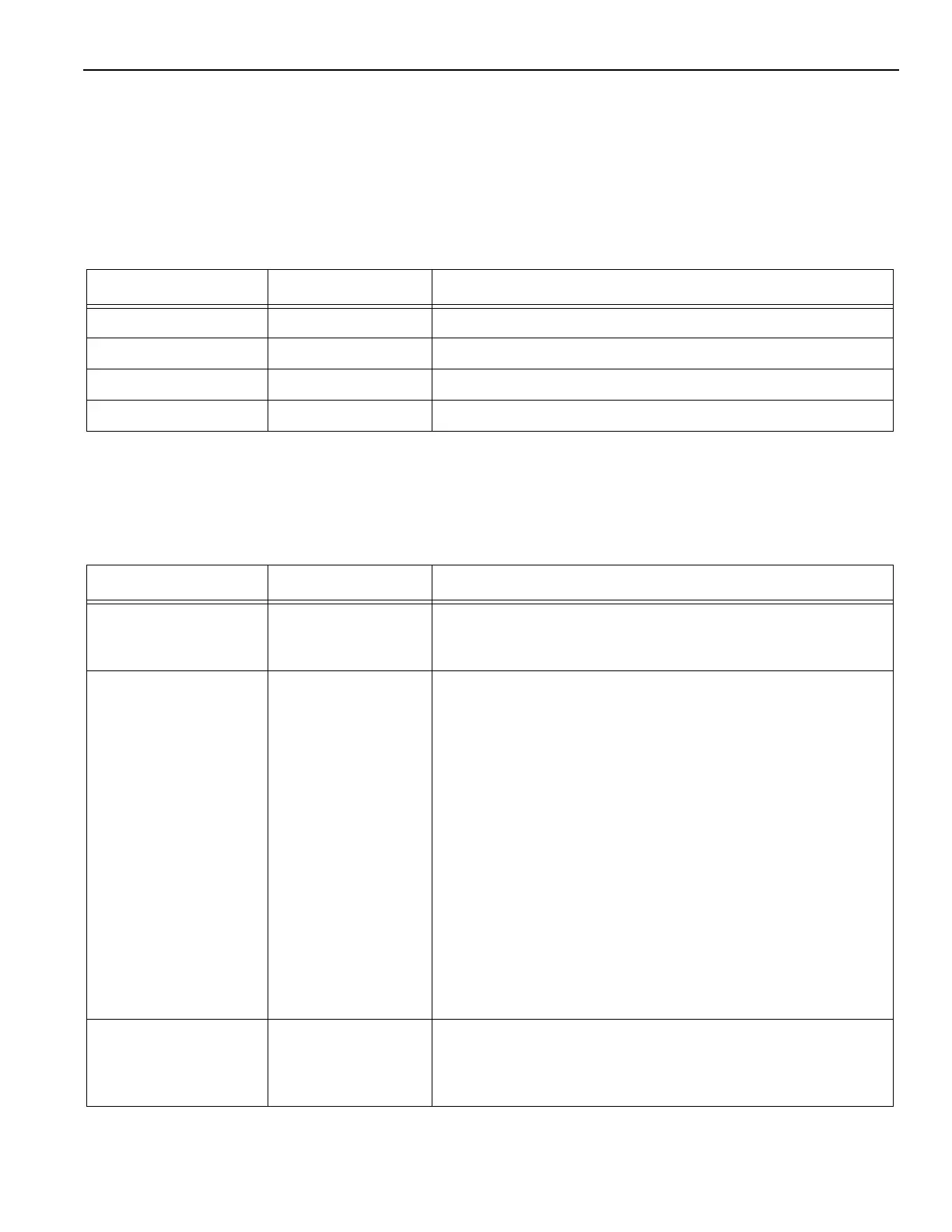
Table 11 outlines the parameters used when using the
clock program to perform scheduled events.
Table 11
Parameter Range Service Level 2 Parameter
P:C0A 0–26 Input channel A. Channel A of the clock with any inverter input.
P:C0B 0–26 Input channel B. Channel B of the clock with any inverter input.
P:C0C 0–26 Input channel C. Channel C of the clock with any inverter input.
P:C0D 0–26 Input channel D. Channel D of the clock with any inverter input.
Parameter Range Service Level 2 Parameter
P:C10 1–50 Choice of switching program. This parameter is used to specify
the program to be used. Works with parameters P:C11 and
P:C19.
P:C11 0–15 Choice of channel. This parameter is used to select the clock
program to be controlled.
0: No channel is activated, deactivated.
1: Channel A
2: Channel B
3: Channel A+B
4: Channel C
5: Channel A+C
6: Channel B+C
7: Channel A+B+C
8: Channel D
9: Channel A+D
10: Channel B+D
11: Channel A+B+D
12: Channel C+D
13: Channel A+C+D
14: Channel B+C+D
15: Channel A+B+C+D
P:C12 0–1 Polarity of channel Parameter shows if the clock program will
switch the selected channel to ON or OFF.
0: Channels will switch OFF
1: Channels will switch ON