INSTALLATION—CONTROLLER
11
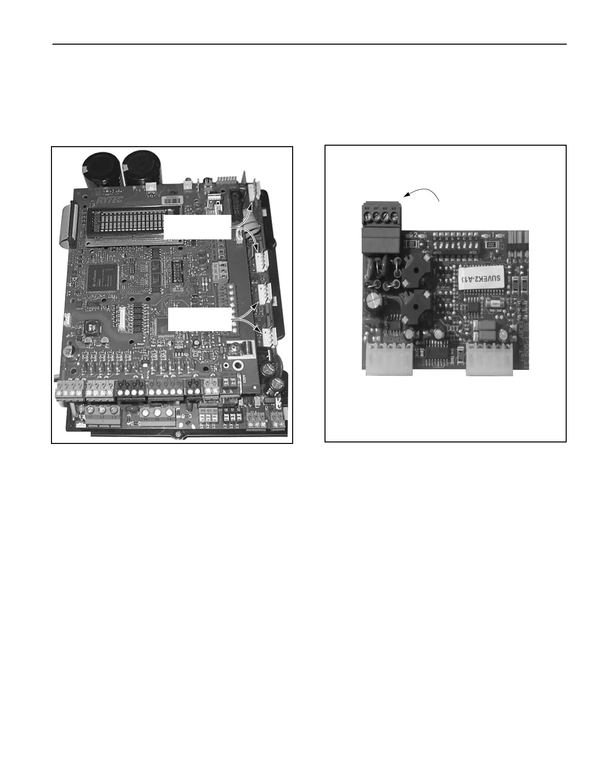
Plug-In Modules
For a door set up to be operated by a radio control or a
floor loop, a corresponding plug-in module for each type
of activator is required. The connectors for these mod-
ules are located along the right edge of the lower printed
circuit board. (See Figure 15.)
Figure 15
NOTE: The induction loop module for the System
4 (part #00122000) is different from the
module for the System 3. The System 4
module is physically smaller. Therefore,
the System 3 loop module will not fit in the
System 4 control. (See Figure 16.)
Figure 16
Radio Receiver
Module
Induction L
oop
Module
A5400016
A5400024
Loop Wire
Te r m i n a l B l oc k