SYSTEM START-UP—SYSTEM RESET (MANUAL RESET)
23
Setting Door Limits (Open, Intermediate, and Close)
1. Access parameter P.210. (See “Navigating Param-
eters” on page 21.)
2. Press the up (▲) or down (▼) key until the desired
door limit option is displayed. Pressing and holding
the enter (●) key will save the displayed option.
NOTE: The RESET key also serves as the
ENTER key and the STOP key.
3. Follow the instructions on the display to set the door
limits.
Setting Automatic Delay Timers
1. Access the Operator Level. (See “Navigating
Parameters” on page 21.)
2. Press the up (▲) or down (▼) key until the desired
delay timer parameter is displayed (P.010 = ACL1,
P.011 = ACL3, P.015 = ACL2).
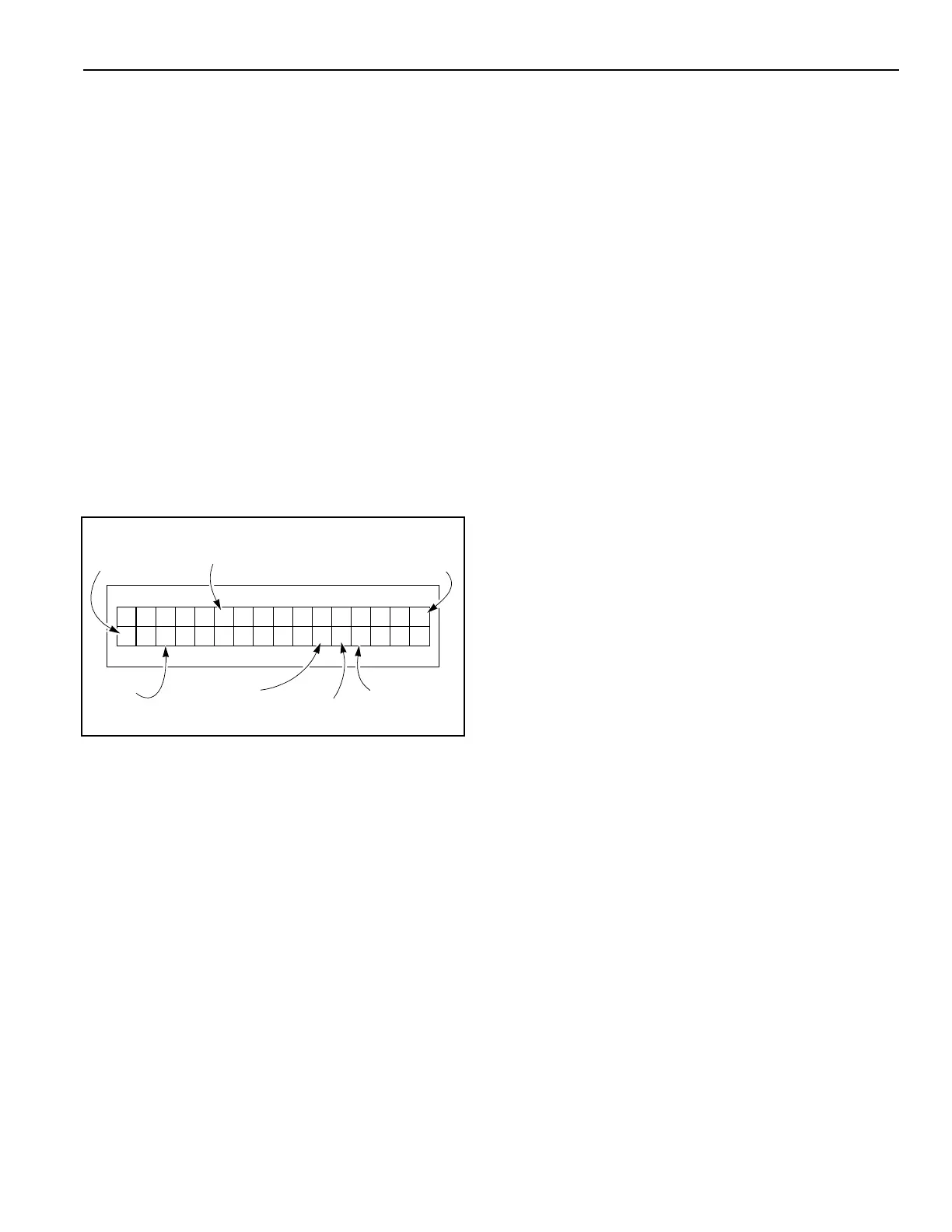
Figure 33 shows that auto-close delay timer ACL1
is currently set with an eight (8) second delay.
Figure 33
3. With the desired timer parameter displayed, press
the enter (●) key to access that parameter. The cur-
sor will jump over to the parameter value.
NOTE: The allowable time delay range for a timer
is 0 to 9999 seconds.
The RESET key also serves as the
ENTER key and the STOP key.
4. Press the up (▲) or down (▼) key to change the
displayed value. Press and hold the enter (●) key to
save the displayed value.
SYSTEM RESET (MANUAL RESET)
A system reset is necessary after the control system
displays an error message and the problem resulting in
that error message has been corrected. To reset the
control system, press and hold the reset (●) key for
approximately three to five seconds. If the display clears
and the message reappears, the problem has not been
corrected and will need further investigation.
NOTE: The RESET key also serves as the
ENTER key and the STOP key.
Once the reset is complete, if the door was is the full-
open or -closed position prior to the error message, the
display will indicate the door type and cycle count. If the
door was in a position other than the full-open or -closed
position, the display will indicate the door is stopped.
After the system is reset, the door can be normally oper-
ated with the up (▲), down (▼), and reset (●) keys.
DEFROST SYSTEM
If your door is configured with an optional defrost sys-
tem, the System 4 Drive & Control is designed to oper-
ate and monitor that system.
See “” on page 28 for additional information on setting
the defrost system controls.
WIRELESS REVERSING EDGE
The wireless system has two main assemblies: the
mobile unit located in the bottom bar under the plastic
cover and the stationary antenna located in the head
assembly. (See Figure 34 and Figure 35.) All mobile
units are installed at Rytec prior to shipping. The wire-
less antenna may or may not be installed by Rytec prior
to shipping. Some Rytec models require the antenna to
be installed in the field. Please reference the specific
product installation manual for your model of Rytec
door. The antenna has a tan-colored cable that runs to
the encoder, which is mounted to the back of the motor,
and a black cable from the encoder that carries the sig-
nals for the reversing edge and the breakaway back to
the System 4 control board.
=
P:A l 1
10 8 #
–
Parameter
Value
Cursor
Operator Level (O)
Service Level 2 (S)
Parameter
Name or Group
Three-Digit
Parameter
Number
Parameter
Status
Unit
Oc
0
9