INSTALLATION—SYSTEM INPUTS
12
SYSTEM INPUTS
The disconnect must be in the OFF posi-
tion and properly locked and tagged before
performing the following procedure.
Input terminals 200 through 293 support
+24 VDC only. All remaining input termi-
nals are dedicated for specific devices.
Connecting any other voltage or device
other than those intended may result in
damage to the control system.
NOTE: If the expansion board is installed in the
controller, there are additional input termi-
nals 300 through 363.
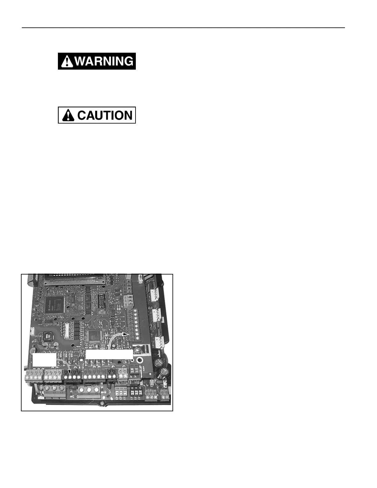
All high-voltage connections (L1, L2, and L3 supply volt-
age wires and the T1, T2, and T3 motor connections)
are made on the lower left terminal blocks. These con-
nections need to be in mettalic conduit entering from the
bottom left corner of the control panel. All low-voltage
connections (+24 VDC) should enter the bottom right of
the control panel and terminate on both the top and bot-
tom circuit boards. (See Figure 17.)
Figure 17
Power Supply Lines
Connect the power supply lines from the fused discon-
nect to the control panel as shown on the schematic that
was shipped with the door.
Motor
Connect the motor wires to the control panel as shown
on the schematic that was shipped with the door.
NOTE: Motor cable cannot exceed 100 feet. Cut
all excess cable to desired length. Refer-
ence the electrical schematic that came
inside the control panel for proper ground-
ing.
Motor Brake
Connect the motor brake to the control panel as shown
on the schematic that was shipped with the door.
Encoder
Connect the encoder to the control panel as shown on
the schematic that was shipped with the door.
External Emergency Stop Switches (N.C. Contacts)
Factory-installed jumper wires are provided in the E-
Stop connections. Refer to the door-specific electrical
schematic for information regarding E-Stop connection.
E-Stop 1 terminals are located at block X24, terminals
240 and 241. E-Stop 2 terminals are at block X25, ter-
minals 250 and 251. E-Stop 3 terminals are at block
X26, terminals 260 and 261.
A5400016
Terminal Block(s)
Te rm in al
Screws