INSTALLATION—CONTROL PANEL INSTALLATION
5
INSTALLATION
CONTROL PANEL INSTALLATION
IMPORTANT: The control panel must be
installed in an area having a tem-
perature range of –4°F to 149°F.
Consult the factory if the temper-
atures approach these limits.
IMPORTANT: The fused disconnect and the
control panel must be installed
within sight of the door.
NOTE: The control panel and fused disconnect
are generally located adjacent to the drive
end of the head assembly.
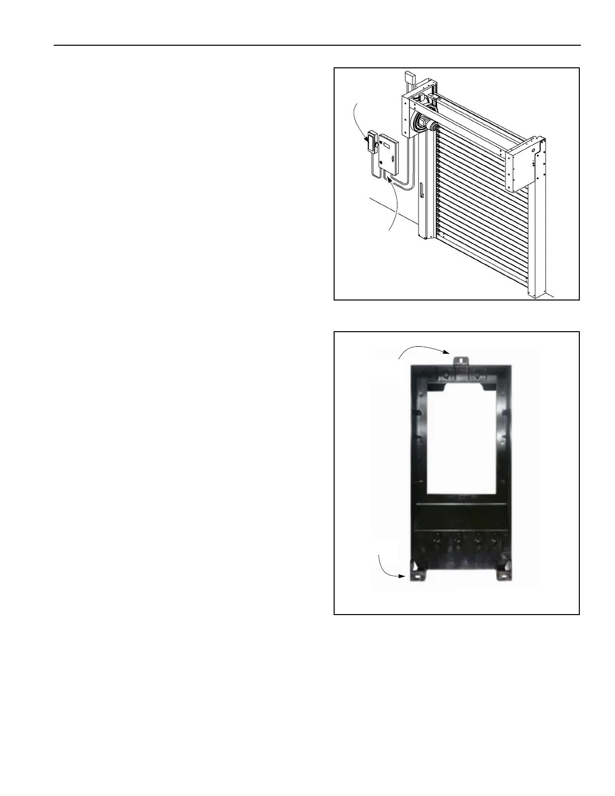
Install the System 4 control panel and the fused discon-
nect as shown in Figure 4.
The System 4 control panel has three mounting loca-
tions on the black plastic enclosure. One is on the top of
the enclosure in the center and two are at the bottom of
the enclosure ( See Figure 5). Use these mounting loca-
tions along with user-supplied hardware to securely
mount the panel at the chosen location.
IMPORTANT: The mounting surface must be
structurally sound and free of
mechanical shock or vibration.
IMPORTANT: All conduit entering the control
panel must enter from the bot-
tom of the panel — High voltage
from the bottom left and low volt-
age from the bottom right.
Installing conduit through the
top or sides of the control panel
will void the warranty.
Figure 4
Figure 5
A9500221
Fused
System 4
Control Panel
Disconnect
Bottom Mounts
Top Mount
A5400020
NOTE: Panel housing shown
.
disassembled for clarity.