INSTALLATION—CONTROLLER
10
CONTROLLER
Located inside the control panel is an electronic control-
ler. This controller includes a scrolling display, terminal
blocks and screws, and other miscellaneous electrical
components. (See Figure 13.)
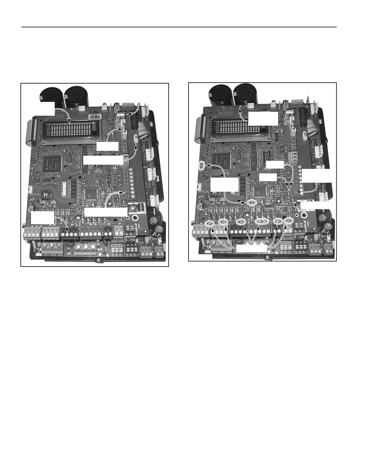
Figure 13
Scrolling Display
All door commands and door status messages appear
on the scrolling display. Also displayed are the cycle
counter, timer settings, alarm conditions, program set-
tings, and other miscellaneous messages.
The display is located near the top of the controller and
can be viewed through the window on the front of the
control panel.(See Figure 13.)
USB Connector
The USB drive logs the function of the door and allows
for programming the door using a Rytec encrypted soft-
ware program. Removing the USB drive will affect the
operation of the door. DO NOT remove the USB drive
unless informed by the Rytec Customer Support
Department to do so.
Status LEDs
Located on the controller are various light-emitting
diodes (LEDs). These diodes are helpful when trouble-
shooting the door and control system. The LEDs indi-
cate the operating status of the control system, the door,
activators, safety devices, and any other input device
connected to the control system. (See Figure 14.)
For detailed information on troubleshooting the control
system using the status LEDs, see “TROUBLESHOOT-
ING WITH STATUS LEDS” on page 52.
Figure 14
A5400016
Scrolling
Terminal Block(s)
Terminal
Screws
Battery
USB Connector
Service Switch
Display
A5400016
Reversing
Edge LEDs
Input LEDs
Run LEDs
(Green)
Red
Green
Ajar LED
24 V Short
LED