SCHEMATICS—GENERAL - BOTTOM BAR CONNECTIONS
62
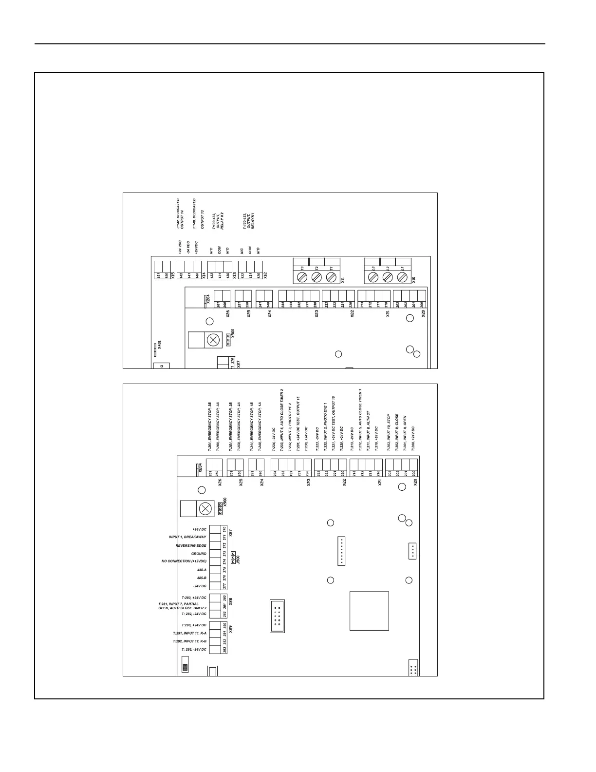
GENERAL - BOTTOM BAR CONNECTIONS
Figure 50
A5400028
NOTE: This schematic is provided for
general information purposes
only. Due to varying require-
ments for individual installations,
another schematic is shipped
with each door and that sche-
matic must be used for that spe-
cific installation.
Encoder and Bottom Bar Connections
Activation Connections, Motion, PC, PB, Etc.
(Optional Equipment)
NOTE: Dashed lines indicate
additional feild wiring
may be required.