INSTALLATION—SYSTEM INPUTS
13
Breakaway Bottom Bar (Input 1 — N.C. Contact)
The breakaway bottom bar signal is incorporated with
the RY-WI wireless reversing edge signal. The break-
away electrical connections are connected to terminals
5 and 6 on the RY-WI mobile unit in the bottom bar. That
signal is then transmitted from the mobile unit to the
antenna located on the head assembly of the door. The
antenna then sends the breakaway signal down the red
wire (encoder cable) to terminal 271 in the controller.
See the schematic that was shipped with the door.
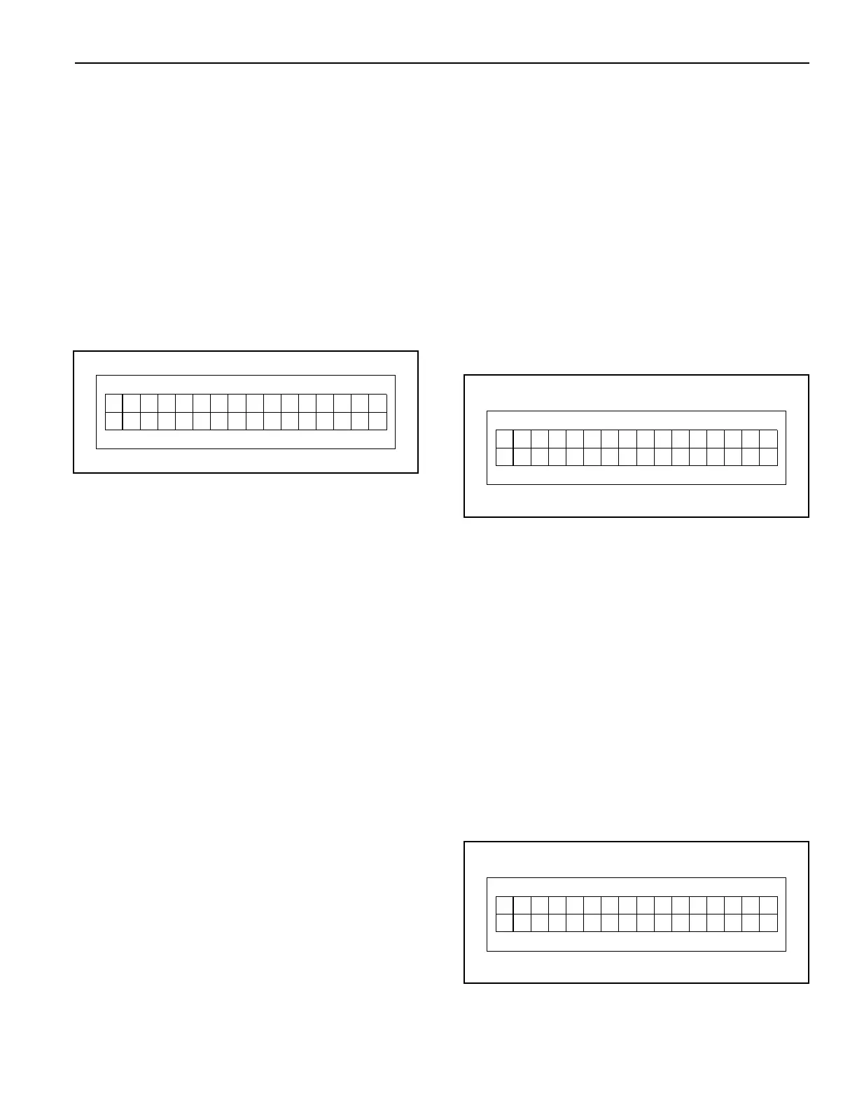
If the bottom bar becomes disconnected from either
side column, a loss of this input will immediately stop
the door and “Door Ajar” will appear on the display.
(See Figure 18.)
Figure 18
NOTE: If you find it necessary to reposition the
bottom bar in order to reattach it, the door
can be jogged up or down by pressing and
holding the up (▲) or down (▼) key.
Push and hold the Stop, Reset and Enter
buttons until the system resets.
Once the bar is reattached and the control
system reset, the up (▲), down (▼), and
reset (●) keys will automatically return to
their normal operation.
Photo Eye — Front (Input 2 — N.C. Contact)
Connect the front set of photo eyes to the control panel
(terminal 222 located on block X22) as shown on the
schematic that was shipped with the door.
An interruption of this input (object between photo eyes)
while the door is closing will reverse the door and move
it to the open position. Only after the object is removed
from between the photo eyes will the door be allowed to
close.
If the door was initially opened by a non-automatic
activator, the door must be closed with a non-automatic
activator. If the door was initially opened by an auto-
matic activator, the door will automatically close after
the auto-close delay timer (ACL1 or ACL2) times out.
(See Figure 19.)
Figure 19
Photo Eye — Rear (Input 3 — N.C. Contact)
Connect the rear set of photo eyes to the control panel
(terminal 232 located on block X23) as shown on the
schematic that was shipped with the door.
An interruption of this input (object between photo eyes)
while the door is closing will reverse the door and move
it to the open position. Only after the object is removed
from between the photo eyes will the door be allowed to
close.
If the door was initially opened by a non-automatic
activator, the door must be closed with a non-automatic
activator. If the door was initially opened by an auto-
matic activator, the door will automatically close after
the auto-close delay timer (ACL1 or ACL2) times out.
(See Figure 20.)
Figure 20
0
Er ro Jog
F06 rooarjA
rlynO
D
t
reld
yo
r
O
e
oo pe
hPe
F
DnH
222
o
t
reld
yo
r
O
e
oo pe
hPe
R
DnH
223
o