PARTS LIST—ELECTRICIAN’S QUICK GUIDE
65
ELECTRICIAN’S QUICK GUIDE
The Rytec System 4 controller is a variable frequency
AC drive. This controller relies on the proper installation
and grounding of wiring and cabling for the controls and
motor. THE HIGH AND LOW VOLTAGE MUST BE SEP-
ARATE. FAILURE TO DO SO WILL VOID THE WAR-
RANTY. A door-specific electrical schematic has been
shipped inside the System 4 control panel. The electri-
cal schematic in this manual is a general schematic and
only used for reference. Use the schematic provided in
the control panel for the actual electrical installation.
NOTE: High voltage is any voltage exceeding 50
volts.
The System 4 control has a class 2 power
supply. Therefore, no voltage from any
other source can be introduced to the Sys-
tem 4 controller.
1. All entries to the control panel must be made
through the bottom of the control panel. Failure to
do so will void the warranty.
IMPORTANT: All conduit entering the control
panel must enter from the bot-
tom of the panel — High voltage
from the bottom left and low volt-
age from the bottom right.
Installing conduit through the
top or sides of the control panel
will void the warranty.
2. High voltage must run in metallic conduit and enter
the bottom left corner of the control panel.
3. All low voltage wiring is supplied by a class 2 power
supply and should be installed in accordance with
NEC and local electrical codes. Failure to separate
high and low voltage will void the warranty.
4. All cables are to be cut to length.
IMPORTANT: Do not bundle or coil excess
cables in the control panel or in
the head assembly of the door.
5. The motor ground (green wire) will terminate to
ground in the control panel. The drain wire (bare sil-
ver) will also attach to ground.
6. The encoder cable will enter the bottom right of the
control panel. The drain wire (bare silver) attaches
under the screw of the P-clip for the encoder cable
(see Figure 45).
NOTE: The encoder cable must be cut to length
and contain no loops or coils.
7. The remaining cable for the photo eyes and activa-
tors must also be cut to length and also contain no
loops or coils.
8. All field electrical work must conform to any applica-
ble local or national electric codes.
9. All field wiring to be minimum 60° C, 600 V rated
copper stranded type.
10. Use shielded cable where indicated on electrical
drawing.
IMPORTANT: Failure to use shielded cable
may result in improper operation
or premature failure and will
VOID the warranty.
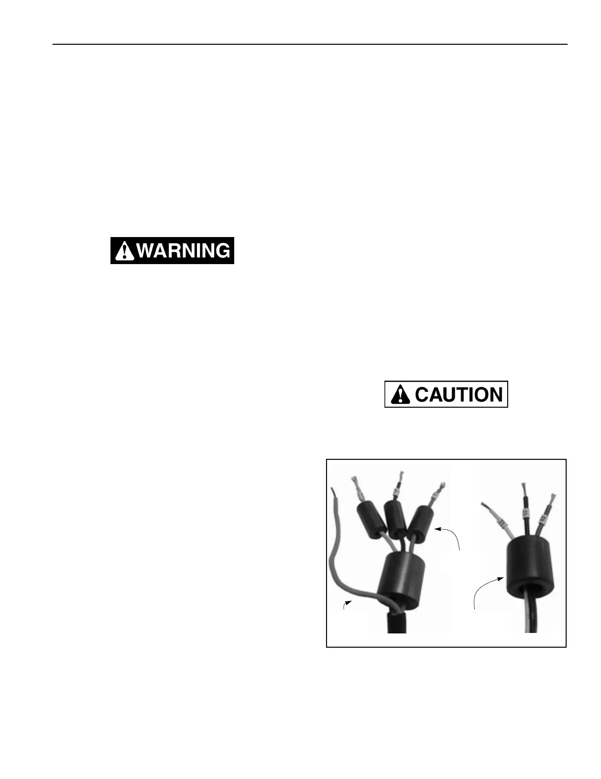
Ferrite core magnets are to be installed on the incoming
L1, L2, and L3 supply voltage wires and also on the T1,
T2, and T3 motor connections. The ferrite core magnets
act as a filter for the incoming supply power and voltage
passing to the motor. These filters help to reduce elec-
trical noise in the power system. See Figure 13 for
proper installation of the ferrite core magnets.
NOTE: Failure to install the ferrite core magnets
as illustrated will void the manufacturers
warranty.
Failure to install the ferrite core magnets will void
the manufacturer’s warranty and potentially cause
irreparable damage to the System 4 control panel.
Figure 53
A5400029-30
Motor Connection
Magnet Location
Supply Voltage
Magnet Location
Green
Ground Wire