SCHEMATICS—GENERAL - ENCODER AND PHOTO EYES
60
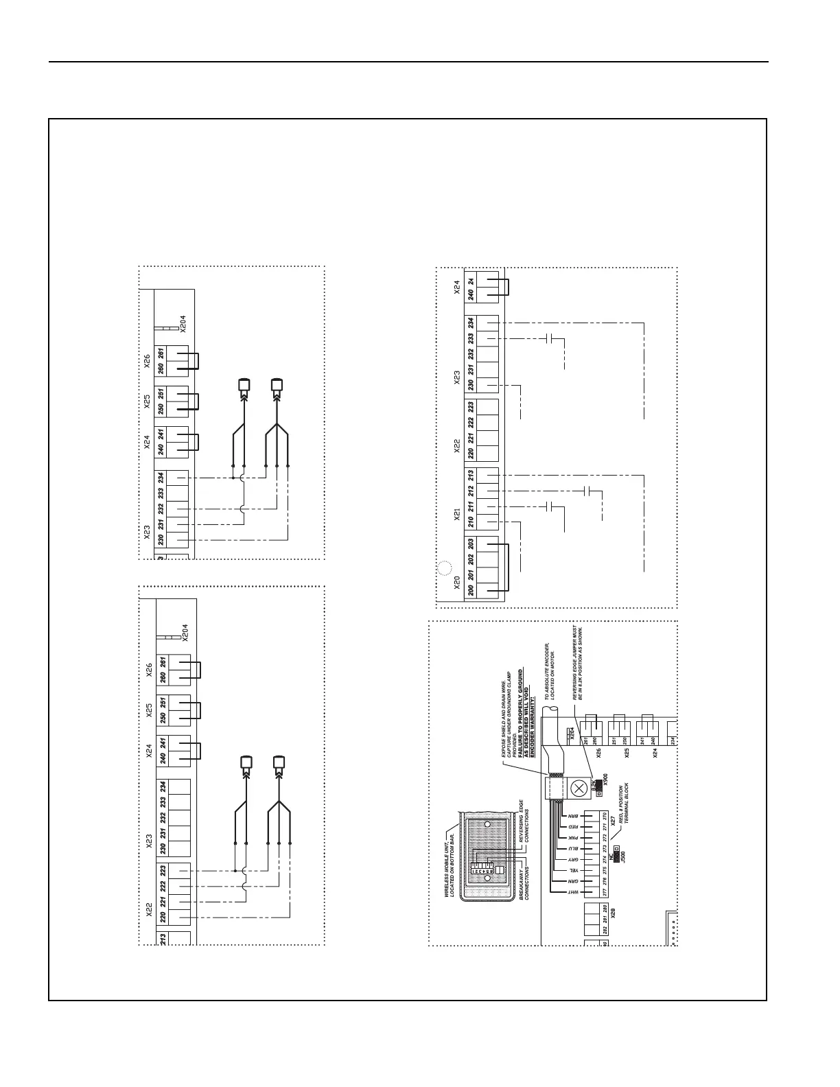
GENERAL - ENCODER AND PHOTO EYES
Figure 48
24VDC+
FOR AUXILIARY DEVICE
POWER AND ACTIVATOR
SIGNAL SOURCE.
24VDC+
FOR AUXILIARY DEVICE
POWER AND ACTIVATOR
SIGNAL SOURCE.
ALTERNATE ACTION
ACTIVATOR, PC, PB
ETC...W/O AUTO CLOSING.
SOURCE, T:210
ACTIVATOR INPUT, PC, PB
MOTION, ETC...W/ AUTO
CLOSING TIMER 1.
SOURCE, T:210
ACTIVATOR INPUT, PC, PB
MOTION, ETC...W/ AUTO
CLOSING TIMER 2.
SOURCE, T:210
24VDC-
FOR AUXILIARY
DEVICE POWER.
24VDC-
FOR AUXILIARY
DEVICE POWER.
PHOTOEYE EMITTER,
REAR.
BLU
BLU
BRN
BRN
BLK
BLU
BLU
BRN
BRN
BLK
PHOTOEYE RECEIVER
REAR, PNP OUTPUT.
PHOTOEYE EMITTER,
REAR.
PHOTOEYE RECEIVER
REAR, PNP OUTPUT.
A5400026
NOTE: This schematic is provided for
general information purposes
only. Due to varying require-
ments for individual installations,
another schematic is shipped
with each door and that sche-
matic must be used for that spe-
cific installation.
Front Photo Eye Connections
Encoder and Bottom Bar Connections
Remote Activation Connections
Rear Photo Eye Connections
NOTE: Dashed lines indicate
additional feild wiring
may be required.