SYSTEM START-UP—WIRELESS REVERSING EDGE
24
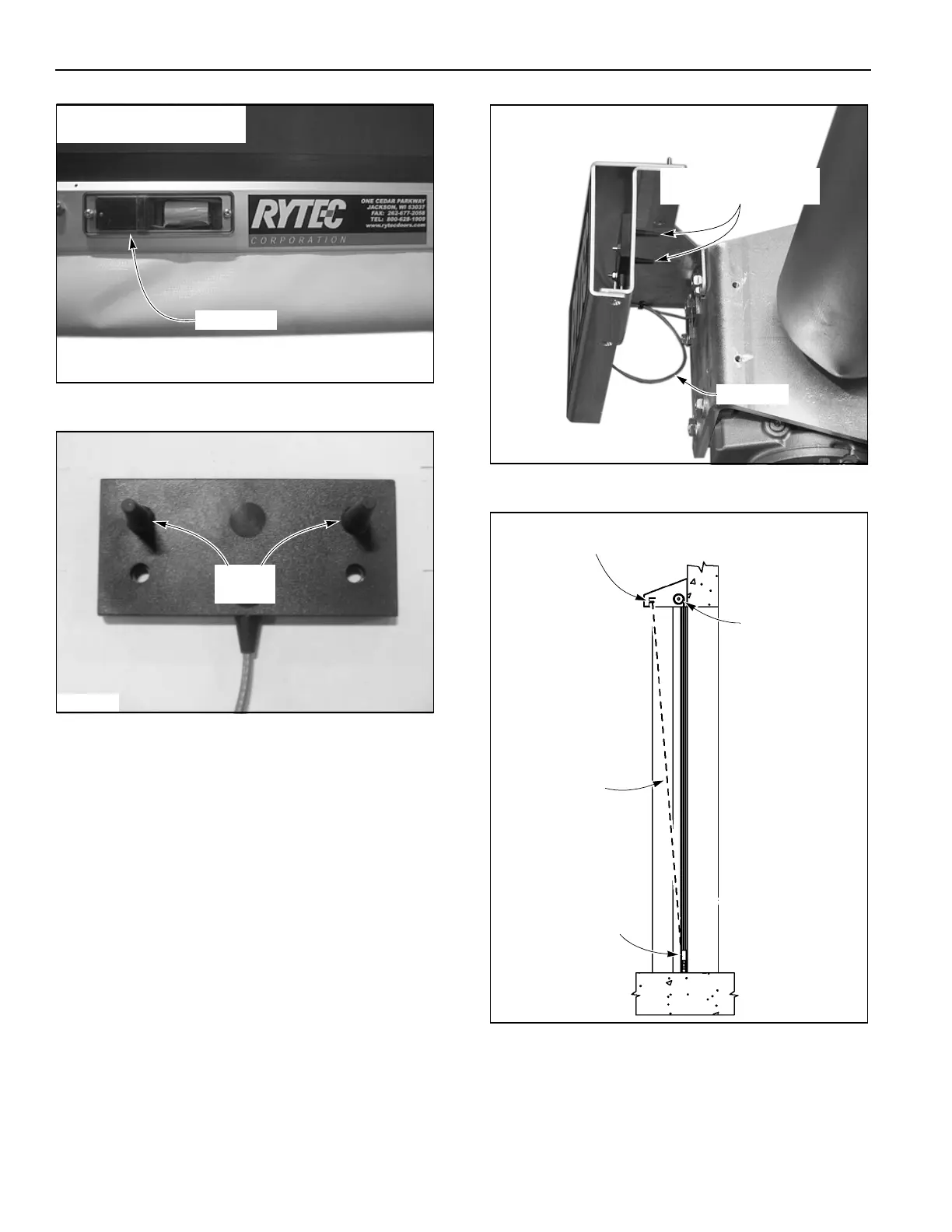
Figure 34
Figure 35
Attached to the electric motor is a small tan-colored
cable. The tan cable is routed from inside the motor
assembly, through the front head assembly, and to the
mounting bracket of the front spreader. When the
bracket is installed, the 2-inch prongs from the antenna
will point toward the drum roll and the tan cable should
exit the bottom of the antenna.
(See Figure 36 and Figure 37.)
NOTE: No bends, kinks, or loops are allowed in
the tan cable. The antenna is fragile and
should be handled with extreme care.
Any leftover packaging material should be
removed from the antenna prior to installa-
tion.
Figure 36
Figure 37
A2500246
Mobile Unit
NOTE: Clear plastic cover is
shown for sample purposes.
A2500247
Antenna
Prongs
A7700019
Antenna Prongs Point
Toward the Drum Roll
Tan Cable
A2500249
Antenna Prongs Point
Toward the Drum Roll
Drum Roll
Mobile Unit
Line of Sight