,
.
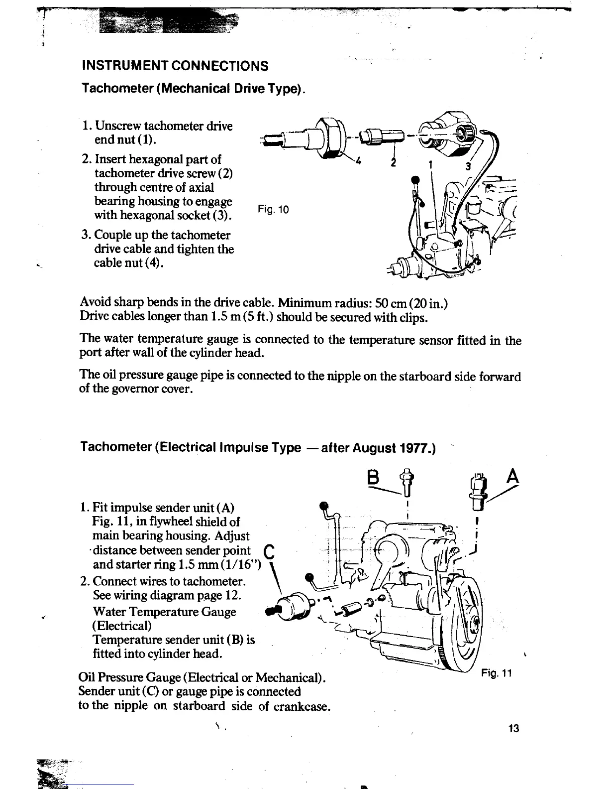
INSTRUMENT CONNECTIONS
Tachometer (Mechanical Drive Type).
. ~
1. Unscrew tachometer drive .~--~_. ~ end nut (1). ~--.l_,~~ I
2. Insert hexagonal part of I. 2 1
tachometer drive screw(2)
through centre of axial
hearing housing to engage F. 10
with hexagonal socket (3). Ig.
3. Couple up tbe tachometer
drive cable and tighten tbe
.. cablenut(4).
Avoid sharp bends in tbe drive cable. Minimum radius: SO cm (20 in.)
Drive cables longer than 1.5 m (5 ft.) should be secured witb clips.
Tbe water temperature gauge is connected to tbe temperature sensor fitted in tbe
port after wall of the cylinder head.
Tbe oil pressure gauge pipe is connected to tbe nipple on tbe starboard side forward
of the governor cover.
Tachometer (Electricallmpulse Type - af ter August 1977.)
1. Fitimpulse senderunit(A) ~, ~p
Fig. 11, in flywheel shield of n --=--;~ ,~. ~
main hearing housing. Adjust f'
~C _~,_I~ !
'distancebe~eensenderpoint, C "-~~~1C" ~ 1.[Jl~.)
and starter nog 1.5 mm(1/16 ')
\ ~ ~ ;-"":. ~l!J G 2. Connect wires to tachometer. ~ ~ .
~I. \ ,I
See wiring diagram page 12. \."". ~ ,').G, ( ') ~~
0' Water Temperature Gauge ~;:s;, "- ~~
~,. -
I~t~' (Electrical) c~ I\~
Temperature sender unit (B) is \:;: '"
fitted info cylinder head. ':j \
Oil Pressure Gauge (Electrical or MechanicaI). Fig, 11
Sender unit (C) or gauge pipe is connected
to the nipple on starboard side of crankcase.
\ . 13
~~~- .