EB 8331-4 EN 5-3
Installation
5.3.2 Construction with ring
nut (formA)
Attachment to Series240 Valves
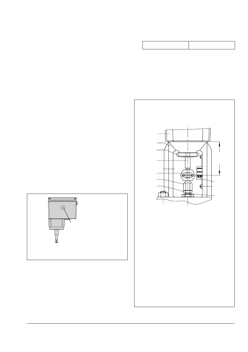
Î RefertoFig.5-5.
1. Push the plug stem down to close the
valve.
2. Turn the stem connector nut (8) until the
dimensionx=75mm(DN100and
larger:x=90mm)fromthetopofthe
yoke to the middle of the stem connector
nut (8) is achieved. Lock this position
with the lock nut (9).
3. Actuator without fail-safe action:
Retract the actuator stem using the manu-
al override (see the 'Operation' section).
Actuator with fail-safe action:
Retract the actuator stem electrically in
the MAN mode (see the 'Operation' sec-
tion).
Actuating shaft
Fig.5-4: Actuating shaft for manual override
(actuator for attachment with ring nut)
4. Place actuator onto the valve bonnet
(2.3) and secure using the ring nut (7).
5. When the stem connector nut (8) rests on
the actuator stem (3), attach both stem
connector clamps (4) and fasten with
screws.
Tightening torque 150Nm
6. Move the actuator stem (3) to the end
position (valve closed) as described in
the 'Operation' section.
7. Align travel indicator scale (10) with the
middle of the stem connector (4) and
screw tight.
Types3374-15/-26/-36
Connection with ring nut (formA)
AttachmenttoSeries240Valves
1
7
3
4
8
9
5
1 Actuator
2.3 Bonnet
3 Actuator stem
4 Stem connector
5 Plug stem
7 Ring nut
8 Stem connector nut
9 Lock nut
10 Travel indicator scale
Fig.5-5: Attachment to Series240 Valves