Display Code Designation Description
Mon MONTH Month
M.dAY DAY OF MONTH Day of month
hour HOURS Hours
Min MINUTES Minutes
SEc SECONDS Seconds
Inter. MINUTE INTERVAL Minute interval (1,2,3,4,5,10,15,20,30,60 min)
Event Flags
EH
FG1.On EVENT FLAG 1 ON Event flag #1 ON
… … …
FG8.OFF EVENT FLAG 8 OFF Event flag #8 OFF
Setpoint Status
SP1.On SP 1 ON Setpoint #1 ON
… … …
SP16.On SP 16 ON Setpoint #16 ON
1
In 4LN3, 3LN3 and 3BLN3 wiring modes, the voltages will be line-to-neutral; for
any other wiring mode, they will be line-to-line voltages.
2
In 4LN3, 4LL3, 3LN3, 3LL3, 3BLN3 and 3BLL3 wiring modes, the voltages will be
line-to-neutral; for any other wiring mode, they will be line-to-line.
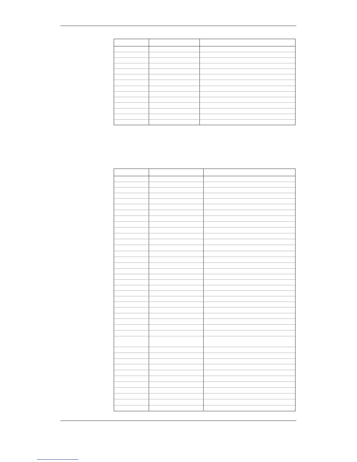
Setpoint Actions
Display Code Designation Description
none NONE None (no action)
rEL.1 OPERATE RELAY #1 Operate RO1
rEL.2 OPERATE RELAY #2 Operate RO2
rEL1.OFF RELEASE RELAY #1 Release latched RO1
rEL2.OFF RELEASE RELAY #2 Release latched RO2
ELoG EVENT LOG
Log to Event Log
E
dLoG.1 DATA LOG #1
Log to Data Log file #1
E
dLoG.2 DATA LOG #2
Log to Data Log file #2
E
dLoG.3 DATA LOG #3
Log to Data Log file #3
E
dLoG.4 DATA LOG #4
Log to Data Log file #4
E
dLoG.5 DATA LOG #5
Log to Data Log file #5
E
dLoG.6 DATA LOG #6
Log to Data Log file #6
E
dLoG.7 DATA LOG #7
Log to Data Log file #7
E
dLoG.8 DATA LOG #8
Log to Data Log file #8
E
32.LoG WAVEFORM LOG #1
Log to Waveform Log file #1
EH
128.LoG WAVEFORM LOG #2
Log to Waveform Log file #2
EH
Inc.Cn.1 INC CNT #1 Increment counter #1
Inc.Cn.2 INC CNT #2 Increment counter #2
Inc.Cn.3 INC CNT #3 Increment counter #3
Inc.Cn.4 INC CNT #4 Increment counter #4
CLr.Cn.1 CLR CNT #1 Clear counter #1
CLr.Cn.2 CLR CNT #2 Clear counter #2
CLr.Cn.3 CLR CNT #3 Clear counter #3
CLr.Cn.4 CLR CNT #4 Clear counter #4
CLr.Cnt CLR ALL CNT Clear all counters
CLr.Enr CLR ENERGY
Clear total and phase energy accumulators
E
CLr.dnd CLR ALL DMD
Clear all maximum demands
E
CLr.P.dn CLR PWR DMD
Clear power maximum demands
E
CLr.A.dn CLR VOLT/AMP/THD DMD Clear volt, ampere and THD maximum
demands
CLr.tEn CLR TOU ENG
Clear TOU energy accumulators
E
CLr.tdn CLR TOU DMD
Clear TOU maximum demands
E
CLr.LHi CLR MIN/MAX Clear Min/Max log
FLG1.On SET FLAG #1
Set event flag #1
EH
FLG2.On SET FLAG #2
Set event flag #2
EH
FLG3.On SET FLAG #3
Set event flag #3
EH
FLG4.On SET FLAG #4
Set event flag #4
EH
FLG1.OFF CLR FLAG #1
Clear event flag #1
EH
FLG2.OFF CLR FLAG #2
Clear event flag #2
EH
FLG3.OFF CLR FLAG #3
Clear event flag #3
EH
FLG4.OFF CLR FLAG #4
Clear event flag #4
EH