Chapter 6 Control system diagram
180 SMSO-2-02.06- 15.07.03
if the standby button is actuated. This means that no fur-
ther product serving is possible, nor can the instant heater
and steam generator heat up.
For reasons of standardisation, the mains voltage is generally
stated as 230V AC in the diagram sheets. Almost all the con-
sumers are designed for an operating voltage of 230 V AC. If
you are working on a mains network of differing voltage , you
must be aware of this when carrying out all test work, and be
aware of the correct results.
The unstabilised control voltage of 36V DC, or the unit control
system voltage of 5V DC is given for the control voltage.
If you are testing a machine with voltage stabilisation circuit,
you must ensure that the control voltage is a constant 30 V
AC.
6.4.2 System test / initial test
Much of the testing and measurement work on the individual
electrical circuits can be carried out only with the initial test. In
some cases, the system test must be used. In principle it is
assumed that service technicians are well practiced in carrying
out this test procedure, and that they will use it whenever it is
possible and sensible to do so.
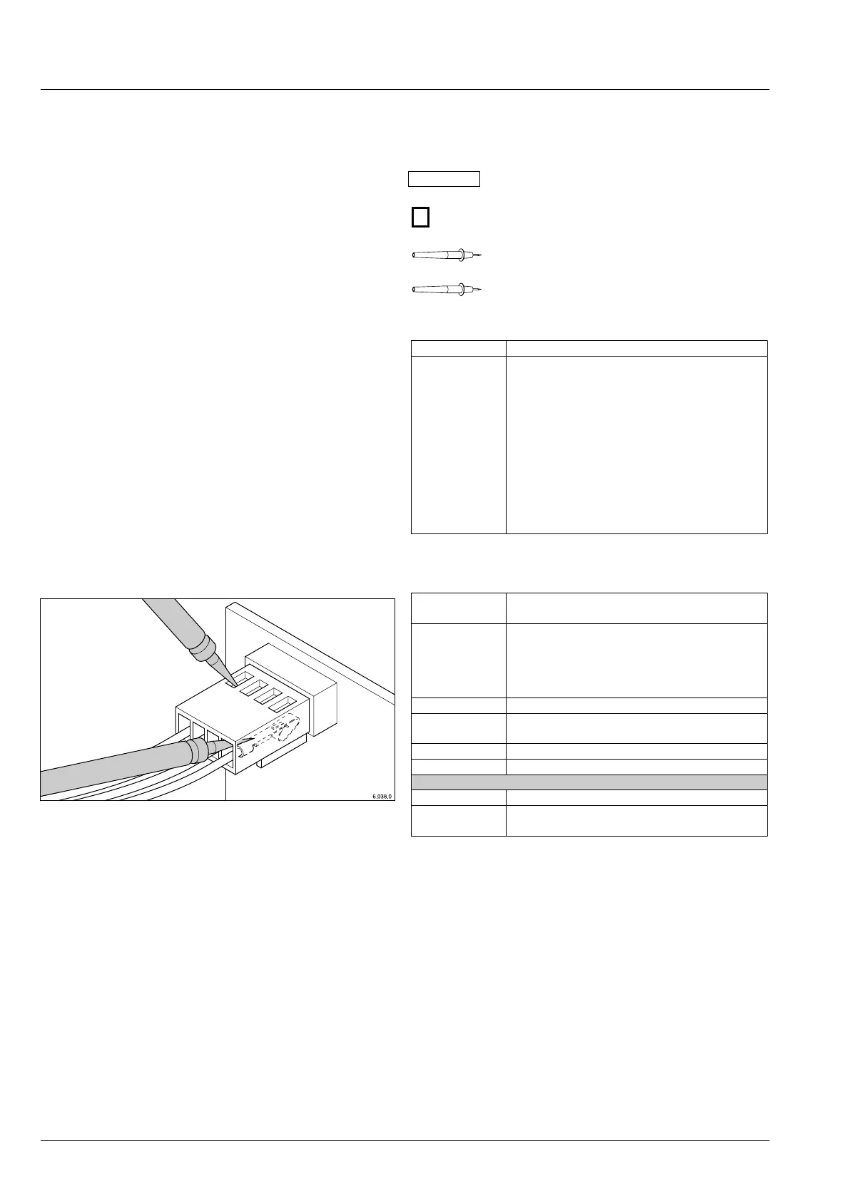
6.4.3 Selecting the test locations
Very often terminals and plugs are the only places where
electrical circuits can be tested. These are often very small
and not very accessible. It is therefore of crucial importance
that you have a range of different and fine test prods so that
you can really get at the live contacts.
Good test prods enable measurements to be made on small
plug shells.
6.4.4 Conventions of presentation
A number of symbols are used in the diagrams, as follows:
230V AC Measured value
1 Work step
Test prod
Next test in another work step
6.4.5 Colour coding for cables
Abbreviation Colour
bl blue
bn brown
ge gelb (yellow)
gegn yellow/green
gn green
gr grey
nc not connected
or orange
r red
s schwarz (black)
v violet
w white:
6.4.6 Electrical circuits / conductor designations
Diagram
Designation
Electrical circuit
L1 Cell connector L1
L2 Cell connector L2
L3 Cell connector L3
N Neutral conductor (live)
PE PE conductor (protective function only)
+ 36 V Direct voltage 36V, not switched
+ 36 V S Direct voltage 36 V switched via relay 1
(main relay)
+5 V Direct voltage 5V control circuit
GND Ground (for all direct voltage circuits)
with voltage stabilising circuit
+30 V Direct voltage 36V, not switched
+30 V S Direct voltage 36 V switched via relay 1
(main relay)