Chapter 3 Functional descriptions
SMSO-2-02.03- 15.07.03 33
3.2.5 Grinder
In the grinder the coffee beans are ground through a three
level grinding unit to become fresh ground coffee. As the cof-
fee beans are crushed, much of the mechanical energy is
converted into heat (friction). The components of the grinder
heat up and in “continuous operation” this heat transfers to the
ground coffee. If the ground coffee gets too warm, the quality
of the coffee can deteriorate. It is therefore very important that
the grinder blades are always in good condition and that the
beans are broken up efficiently and not crushed.
(NOTE: At an average grinding time of 4.5 seconds per coffee,
80,000 cups will signify approximately 100 operating hours).
Functional description
The two grinder blades are mounted horizontally. The lower
grinder blade sits on a star shaft at the base of the grinder
housing, and it is driven by means of a worm gear motor. The
upper grinder blade is mounted with a threaded bush so as to
be adjustable axially and does not rotate.
By adjusting the upper grinder blade axially the air gap be-
tween the two grinder blades can be adjusted very accurately.
This air gap defines the grain size of the ground coffee, what
is known as the grinding degree.
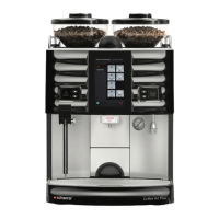
The grinding degree setting (the distance between the grinder
blades) is made manually on a “worm gear” which engages on
every quarter turn, and is thus secured against coming loose
(losing its setting). The powder (ground coffee) is discharged
into the powder outlet through four cams attached evenly
around the circumference of the star shaft. A wire at the end of
the powder outlet ensures that the fresh ground coffee falls
into the brewing unit powder inlet in a controlled fashion.
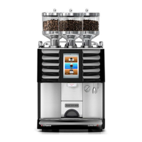
The control system monitors the operating status of the
grinder via the motor current . A grinder running empty, bean
container empty (=low grinding resistance) or foreign bodies in
the grinder (very high grinding resistance) etc. will affect the
current consumption by the motor, which is detected and the
grinder switched off. A relevant error message appears on the
display.
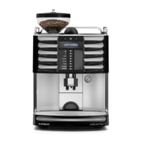
Grinder
1 Grinder housing
2 Star shaft
3 Lower grinder disk
4 Upper grinder disk
5 Upper part of grinder
6 Grinding degree disk (setting scale)
7 Worm gear
8 Powder outlet
9 Coffee beans
10 Ground coffee (coffee powder)
11 Motor / gear
12 Rubber / metal buffer
13 Visual check during service
Technical data
Nominal voltage: 24 V DC
Operating voltage: 30-36 V DC
Operating current: 5-6 A
Idle current: 1-1.6 A
Current when “grinder empty”: < 1.45 A (corresponds to
value 50 in the program-
ming system)
Current when “grinder blocked”: <8A for 1 second or
<8.4A for 0.2 seconds
Grinding degree setting
Drawing symbol
Illustration
Grinding degree setting
Number of clicks of the grinding
degree disk (take note of the directi-
on of rotation).
+/- 10 % 5
+/-20 % 10
+/- 30 % 15
+/- 40 % 20
+/- 50 % 25
over 50% Readjust the grinding degree disk