Chapter 6 Control system diagram
SMSO-2-02.06- 15.07.03 207
6.5.21 Rotary-vane type pump, motor
36V 5V DC
36V S
L1, N
Operating condition
When the voltage supply is functioning correctly, the rotary vane type pump operates for a certain period for all product serv-
ings.
Symptoms
The rotary vane type pump motor is not functioning.
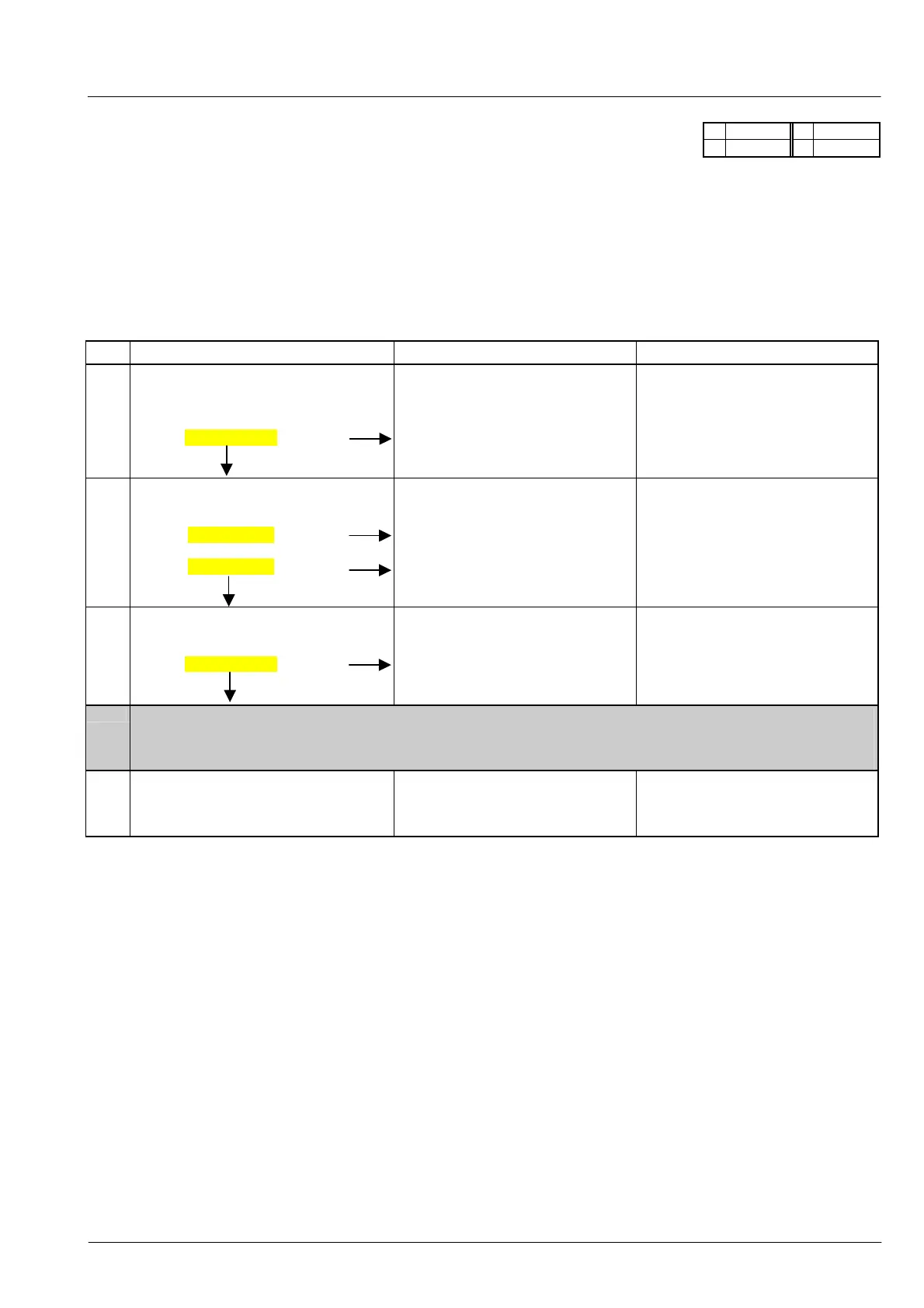
Procedure
Process
step
Check Possible cause Remedy
1
Take voltage measurement at the
connection terminals to the ma-
chine:
L1, N:
Mains voltage ?
Check the mains connection (see
“mains connection”)
Fault in mains connection
2
Measure voltage at power PCB
input at control fuse F1:
Input (top), N
Mains voltage ?
Output (bottom), N
Mains voltage ?
Cable broken or pulled out of
terminal / plug
Plug contacts on power PCB
(input) faulty / oxidised
F1 fuse faulty
Replace cable or reinsert it into
the terminal
Check / replace the plug contacts/
cable
Replace fuse F1
3
Carry out initial test:
Take voltage measurement at the
terminals to the motor cable:
Mains voltage ?
Plug contacts on power PCB
(output) faulty / oxidised
Cable broken or pulled out of
terminal / plug
Relay 3 faulty
Check / replace the plug contacts/
cable
Replace cable or reinsert it into
the terminal
Replace the power PCB
Capacitors can be tested only on special measurement instruments.
The capacitor on the motor causes a rotary field to generate in the stator coil. If the capacitor is faulty, the motor makes
a “buzzing” noise and becomes hot, but the motor shaft (pump) does not rotate.
Resistance measurements etc. are not meaningful and thus pointless.
4
The motor buzzes but the shaft
does not rotate:
Faulty capacitor
Motor / pump mechanically blo-
cked
Replace the capacitor
Test the motor/pump individually;
replace faulty components (see
section 5)
NO
YES
NO
NO
YES
NO
YES