Chapter 3 Functional descriptions
SMSO-2-02.03- 15.07.03 61
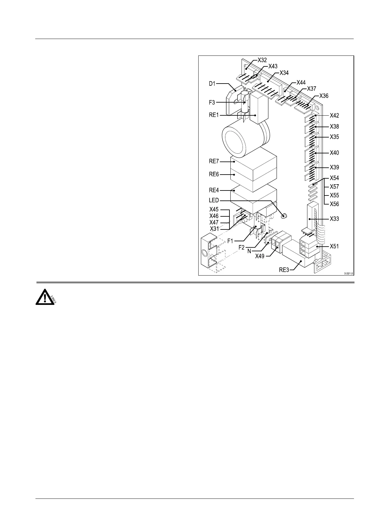
3.2.20 Power PCB
The Power PCB is the power distributor for the machine and
thus the interface between the unit control system and the
consumers. It contains almost all the elements required to
switch the consumers (motors, heaters, valves etc) either
direct or via additional power relays. The power PCB also
contains the power supply, the 36V DC supply with the fuses,
the separately mounted toroidal core transformer and the
rectifier.
The high current for the heaters in the instant heater and the
steam generator is provided via the separate relays.
Function
As soon as the machine is connected to the mains network
(main switch on), 36V DC voltage is generated in the power
supply of this PCB; the LED is lit. This voltage supplies most
of the motors, the cup plate heating and the solenoid valves.
The heavy users of power such as the heaters and the pump
are operated by the power relays at 230 V AC.
The unit control system has its own stabilised 5 V DC voltage
supply located on the unit control system PCB.
The motors and solenoid valves are switched on and off by
electronic switches (=power transistors, semi-conductor
switches) In transistorised circuits the current can be con-
ducted in different ways, the circuit type selected here is the
emitter circuit (see panel).
The rectifier and the power transistors get fairly hot especially
if they are in continuous operation. This heat loss must be
able to dissipate without hindrance. For this reason machines
should be erected so that sufficient cool air can circulate
through the ventilation slits. The power PCB, the toroidal core
transformer and the unit control system are not cooled directly
by the ventilator installed in the rear wall of the machine!.
DANGER TO LIFE / MATERIAL DAMAGE
When carrying out any work on electrical
appliances, fatal injuries may be caused by
electric shock, if live parts are touched.
Even at low voltages, contact with live parts
can also cause bodily harm to people, Such
work must be carried out only by authorised
and qualified electricians.
Static discharge caused while working on the PCBs
can destroy them. When handling PCBs make sure
that they cannot suffer electro-static discharge and
always store susceptible components in anti-static
packaging.
Safety fuses protect connected appliances from cur-
rent surges when an overload occurs, or in the event
of a short circuit. If the fuse values are too high, a
fault could cause material damage or a fire. Safety
fuses should therefore only be replaced with fuses
having the same nominal values.
Technical data
Primary voltage: 110 V AC ± 10 %
230 V AC ± 10 %
Secondary voltage, transformer: 24 V AC
Secondary voltage: 36 V DC
Transformer power: 120 VA
Primary fuse: 110 V: 3.15 A T
230 V: 2.0 A T
Secondary fuse: 8.0 A T
Stabiliser
Primary voltage: 110 V AC ± 10%
230 V AC ± 20%
Secondary voltage, transformer: 42 V AC
Secondary voltage, stabilised: 30 V DC
Transformer power: 140 VA
Voltage stabilising circuit
If there are large voltage fluctuations in the mains network, the
consumer voltage must be stabilised to a constant value by
means of an additional circuit. To this an appropriate toroidal
core transformer, together with an electronic stabilising circuit,
is fitted instead of the standard toroidal core transformer, This
circuit supplies a constant voltage of 30 V DC to supply all the
DC consumers.
When taking voltage measurements in the power electronics,
you should also note whether a voltage stabilising circuit is
present or not; the voltage values differ.