4 Connecting the Device
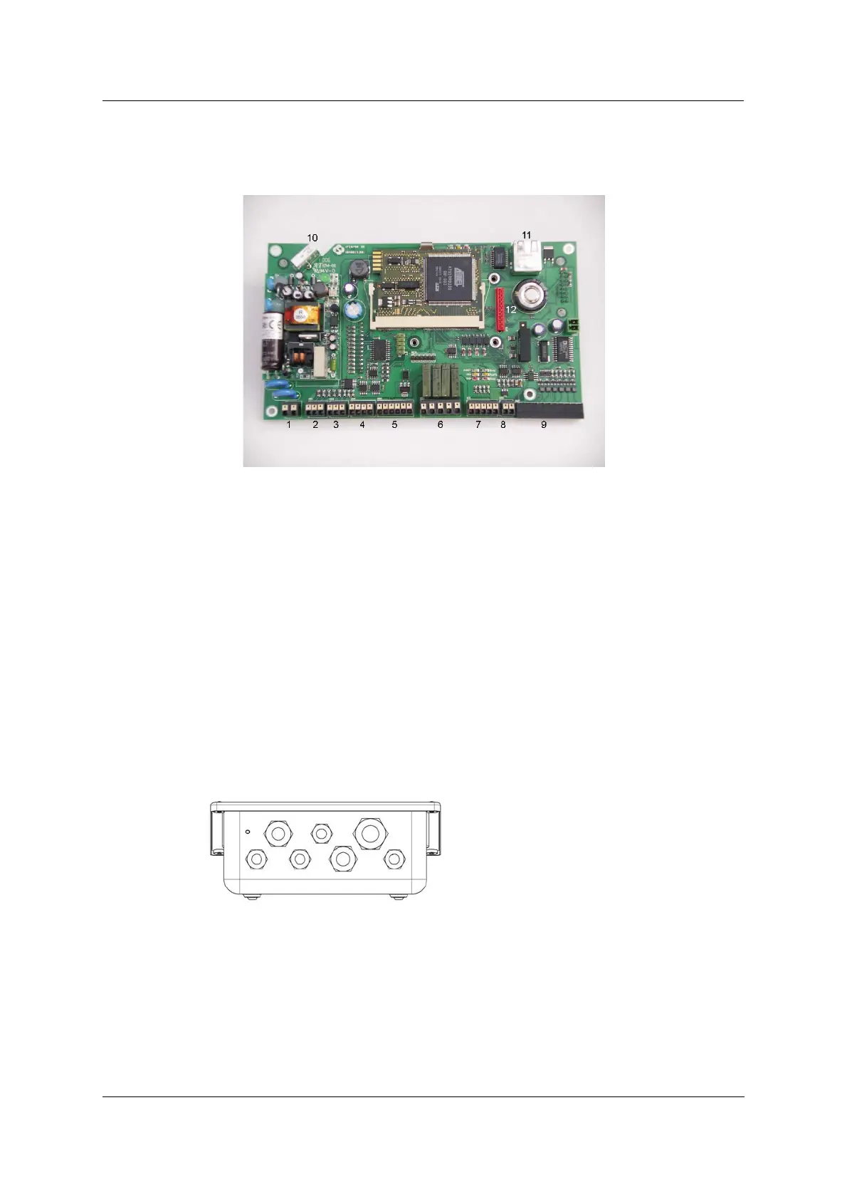
Figure 3 shows the location of the terminals
Connecting the Device
INTECONT® Satus Operating Manual BV-H2346GB / 0833 5
© Schenck Process
Fig. 4
1: Power supply (mains voltage)
2: Serial interface S1 (RS 232) - reserved for service-
program EasyServe
3: Serial interface S2 (RS 232) - unused
4: Serial interface S3 (RS 485) - reserved for Fieldbus-
communication MODBUS
5: Namur inputs/pulse-output point
6: Digital outputs
7: Digital inputs
8: Analog output - reserved for actual production
9: Load cell connection
10: USB CONNECTION - unused
11: Network connection (Ethernet)
12: Connector for optional Fieldbus module
Screened lines (load cell connection, serial interfaces) are bared in the device and
attached to the rail with isolated clamps for pull-relief.
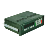
Fig. 5: