Do you have a question about the Schenck process Intecont Plus Belt Weigher and is the answer not in the manual?
Description of the INTECONT PLUS system and its applications.
Description of the INTECONT PLUS display capabilities.
Description of the LED indicators on the INTECONT PLUS.
Description of the INTECONT PLUS keyboard functions.
Explanation of how the belt weigher measures feed rate.
Details on the measurement techniques used by the INTECONT.
Describes system behavior during and after power application.
Explanation of the signal lamp indicators and their meanings.
Details on message E1, indicating power failure status.
Explains how to control the system in normal operation.
Procedure for testing displays and checking software version.
How to enable batching mode but not start a batch.
Procedure for entering batch setpoints manually or via external input.
How to remove batching mode and add material to batches.
Using visual make-up trick and keyboard mode for control.
How to print batch reports automatically or manually.
How to print the complete parameter list with current values.
Explanation of the printed feed rate diagram.
Describes the process and results of the zero setting program.
Lists and explains event messages related to zero setting.
How parameters are organized, named, and identified.
Differentiates parameter types and how to access the parameter menu.
How to start and stop the weighing process using various methods.
Explains reset, function access, and navigation keys.
Explains how belt load is measured and processed.
Details on acquiring and using belt speed data.
How feed rate is calculated from load and speed.
Shifting measurement to discharge point using delay elements.
How batching mode operates with preselected material amounts.
Control of batching using the material prefeeder.
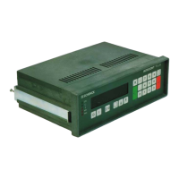
Technical details for the panel-mounting version.
Specifications for housings and operating environment.
Information on power supply, connectors, and control outputs.
Specifications for analog signals, pulse counter, and printer.
Details regarding the connection and specifications for load cells.
Behavior during power failure and language/unit selections.
How displays, signal lamps, and event messages indicate system status.
Multi-level menu operation and belt speed measurement characteristics.
Characteristics related to belt speed measurement and zero setting.
Characteristics of batching, belt drift, and zero drop out.
Configuration of limit values, filters, and maintenance hints.
Access to SPC data and system adaptation features.
Lists digital inputs and outputs with default values and functions.
How to access and navigate setting programs via the distributor.
Details on the Belt Circuit LB program for initial calibration.
How to interpret results from the Weight Check CW program.
How to change date and time settings.
How to check scale functions without material.
Displays for version, hardware, option card, date, and time.
Details on input/output switching conditions and load cell values.
Lists values for load cell, mean value, and variance.
Lists counter status, software checks, and BIC counts.
Overview of parameters, units, limits, and data.
How default parameters are set and how parameters are identified.
Differentiates parameter types and how to access the parameter menu.
Procedure for inputting parameter values using keypad.
How to load default settings and the effect of power failure.
Configuration for fieldbus, feeder, monitoring, and events.
Parameter for event class V-MAX.
Parameters for printing results, ZDO, and zero set difference.
Parameters for belt empty, batch setpoint tolerance, and batch source.
Parameters for resetting print counters and setting print page layout.
Setting for the SPC filter time.
Parameters for data format, address, and resolution.
Parameters for DeviceNet address, baud rates, and hardware selection.
Parameters for sensor length, width, offset, drift, skew, and slip.
Parameters for slip events, digital outputs, and freeze BIC.
Event parameters for load cell input, simulation, and external events.
Digital outputs for batch status, feed modes, and keyboard.
Parameters for reading belt load, belt speed, and counter.
Lists and explains system-related event messages.
Lists and explains electrics-related event messages.
Messages for falling below minimum limit values.
Explanation of signal lamps for power, CPU, alarm, and limits.
Basic steps for operating the INTECONT for the first time.
How to interpret events and adjust parameters for initial setup.
Utility of check weights and procedure for verification.
Performing accurate weighing with material and subsequent correction.
Setting up belt run monitoring with sensors.
Shifting measurement to discharge point using delay elements.
Dialog language, display units, and parameter conversion.
Nominal feed rate, characteristic value, and counter display settings.
Calibration data entry for belt length and inclination.
Configuration for scale monitoring and event classes.
Steps for starting the weigher and interpreting initial displays/messages.
How to check tachometer, load cell, and belt load signals.
Performing accurate weighing with material and subsequent correction.
Setting up belt run monitoring with sensors.
Shifting measurement to discharge point using delay elements.
Using a test plug to check INTECONT operation.
Explains different control modes for starting and stopping.
Schedule of parameters for batching without clearance.
FF/DF change-over, adaptation, release, alarm, and power down procedures.
Parameters for dribble feed, cut-off points, and feeder activation.
Reference for nominal feed rate and summary of operating principle.
Setting LB program for weighers without speed measurement.
Wiring diagram for the base card connectors.
Wiring for interfaces (RS232, RS485) and EasyServe.
Wiring diagram for option card connectors.
Guidelines for cable routing, shielding, and fastening.
Notes on connector types and rear view layout.
Importance of effective platform length for calibration.
Descriptions of single-idler and multi-idler platform types.
Description of the buckled platform configuration.
Details on serial interface and DIP switch settings for printers.
Steps and considerations for replacing FIP with VEG units.
Diagrams showing FIP base and option card connections.
| Type | Belt Weigher |
|---|---|
| Protection Rating | IP65 |
| Application | Continuous weighing of bulk materials |
| Accuracy | ±0.5% to ±1% |
| Belt Width | 400mm to 2400mm |
| Material | Steel (various grades depending on model) |
| Capacity | Up to 10, 000 t/h |
| Output Signal | 4-20 mA |
| Power Supply | 115/230 VAC, 50/60 Hz |