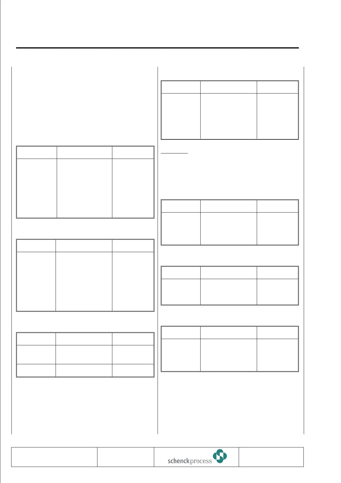
The FIP base and option cards connection diagrams
indicate for every digital input and output the relevant
INTECONT VEG parameter numbers used for
distribution on physical signals.
The tables below compares the connector
assignments of FIP and VEG for all physical signals.
Digital Outputs
FIP Physical Signal VEG
X1 1,2
X1 3,4
X1 5,6
X6 1,2
X6 3,4
X6 5,6
X6 7,8
X6 9,10
DA1
DA2
DA3
DA4
DA5
DA6
DA7
DA8
X1 1,2
X1 3,4
X1 5,6
X8 1,2
X8 3,4
X8 5,6
X8 7,8
X8 9,10
Digital Inputs
FIP Physical Signal VEG
X3 1,2
X9 1,2
X9 3,4
—-
—-
X3 5,6
X5 1,2
X3 3,4
DE1
DE2
DE3
DE4
DE5
Sensor = (DE6)
V1 (Tacho 1) = DE7
V2 (Tacho2)
X3 1,2
X3 3,4
X6 6,7
X9 1,2
X9 3,4
X3 5,6
X7 1,2
—-
Analog Inputs/Outputs
FIP Physical Signal VEG
X9 9,10
—-
A01
A02
X6 4,5
X9 5,6
—- AI X6 1,2,3
Load Cell
FIP Physical Signal VEG
X5 3
X5 4
X5 5
X5 6
X5 7
X5 8
OUT1
REF1
IN2
IN1
REF2
OUT2
X7 3
X7 4
X7 6
X7 5
X7 7
X7 8
Attention:
Signals IN1 and IN2 are swapped between FIP and
VEG. (VEG is compatible to DISOCONT).
Power Supply
FIP Physical Signal VEG
X2 1
X2 2
X2 3
X2 4
0V ext
24V ext
ext. 0V supply
ext. 24V supply
X2 1
X2 2
X2 3
X2 4
Printer
FIP Physical Signal VEG
X8 1
X8 2
X8 3
Screen
TX
RX
X10 1
X10 2
X10 3
Pulse Output
FIP Physical Signal VEG
X9 5
X9 6
X9 7
X9 8
24V
Open collector
Open emitter
0V
X6 8
X6 9
X6 10
X6 11
With VEG, fieldbus is connected via separate fieldbus
cards (FIP: Connector X7). See Fieldbus Manual
BVH2220.
0837
VBW INTECONT PLUS
Replacement Instructions
BV-H2214 GB 112
Technische
Redaktion PDE-RD
Transmission to third parties and reproduction of
this documentation are not permitted. Schenck
Process GmbH reserves all rights of ownership
and copyrights.
 Loading...