Automatic Zero Setting
Activate the automatic zero setting function only in
clearly defined cases, e.g. if some belt circuits are run
with no load.
Parameter H 01 = JA Automatic active
= NO Automatic not active
Automatic system is active both in turned-on and
turned-off state of scale, if belt speed exceeds Vmin.
Measuring result of one belt circuit is continuously
compared to previous result.
If “Belt Empty” is identified, zero point is automatically
corrected.
Set continuous plausibility check with Parameters H
02 and H 03. For normal conveyor belts, default
values can be used, however, a check is
recommended.
1. Deactivate automatic H 01 = NO.
2. Call zero setting program via function distributor
various times and acquire result.
3. Note final results Dev. (upper display) as of
second run.
4. The highest value of Item 3 is the smallest value
for Parameter H 02.
Enter double to triple value, but min. 0.1 %.
.
5. Parameter H04 monitors the total of all zeroing
operations. Enter value, e.g. 2...4 times higher
than H 02.
6. Activate Automatic using Parameter H 01.
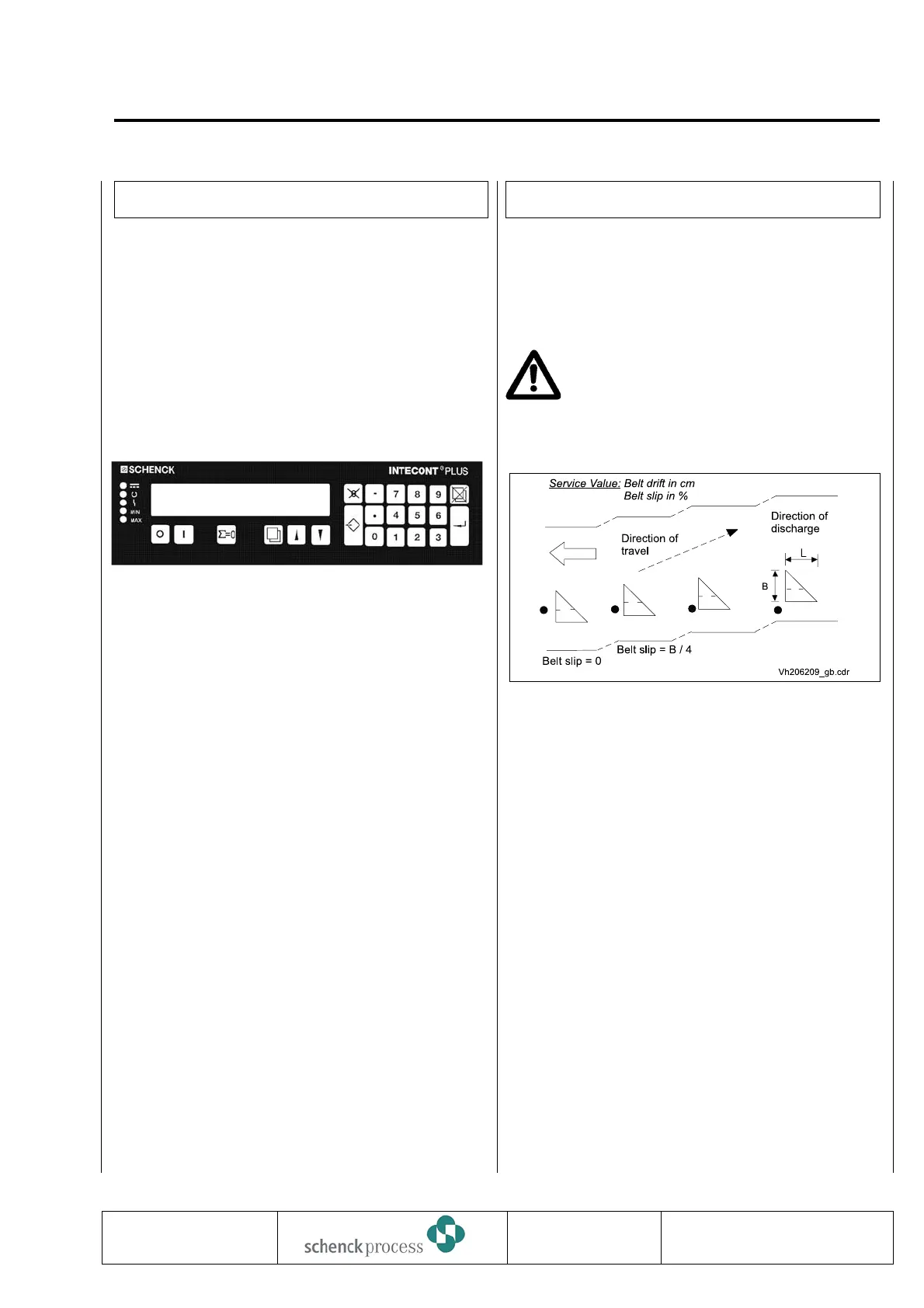
Belt Run Monitoring
INTECONT comes with belt a belt run monitoring
function designed to detect belt drift and belt slip.
Activate monitoring using Parameter N03 “Belt Sensor
Active”.
The belt run monitoring functions can be used only if a
belt circuit sensor (Namur transducer) and
a triangle metal sensor area on belt area
available (see Fig. Below). If not,
Parameters N03 “Belt Sensor Active” and
N05 “BIC Active” must be set to “NO.
To activate belt run monitoring:
1. Set Parameter N03 “Belt Sensor Active” to
“YES”.
2. Enter sensor length L into Parameter N06
“Sensor Length” (s. Belt Run Monitoring figure).
3. Enter sensor width B into Parameter N07
“Sensor Width” (s. Belt Run Monitoring figure).
4. Set Parameter N08 “Sensor Offset” to 0.
5. Call calibrating function “LB: IMP/Belt”.
6. Acquire result after min. 2 belt circuits.
7. Adjust sensor.
Note: Service value ”Imp.S” indicates the
number of pulses measured for the covered
sensor. If the belt sensor is located exactly in mid
sensor area, the following value results:
Imp.S. = 0.5 * L (N06) * 0.01 * vs_Charact. Val.
(B04)
Example: N06 = 8.40 cm and
B04 = 1000 I/m result in Imp.S. = 42
0837
INTECONT PLUS VBW
Commissioning
BV-H2214 GB 91
Transmission to third parties and reproduction of
this documentation are not permitted.
SchenckProcess GmbH reserves all rights of
ownership and copyrights.
Technische
Redaktion PDE-RD
Z1 = 2500 kg
I = 0 kg/h
Fig.: Belt Run Monitoring
 Loading...