Block C : Calibrating Data
C01 Belt Circuit No.
Range: 1...100 Default: 1,00
lets you determine the run time of the Zero Setting,
Taring and Weight Check setting programs.
Does not apply to AUTO Zero Set.
C02 Belt Circuit Time
Range: 1,0...9999,0 s Default: 30,0 s
lets you determine the measuring time for the
“Imp/Belt Circuit” calibration program.
Normally, the time is selected for one belt circuit.
C03 L/C Charac. Value
Range: 0,01...9,9999 mV/V Default: 2,8500 mV/V
indicates the load cell characteristic value
(transmission factor).
C04 L/C Rated Cap.
Range: 0,5000...
220 000.0 kg
Default: 220,000 kg
indicates the total of load cell rated capacities.
Pivots are considered as load cells.
C05 Eff. Platf. Length
Range: 0,1000...50,000 m Default: 1,000 m
indicates effective length of weighing platform.
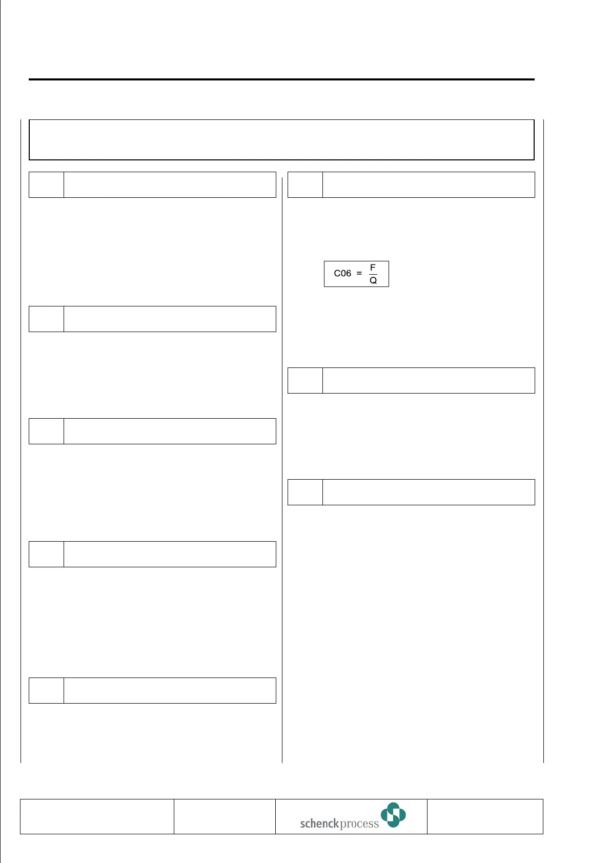
C06 Lever Ratio
Range: 0,0100...2,0000 Default: 1,0000
Lever ratio of force transducing weighed idler of
platform and load cell.
Q = platform load
F = load on load cell
With weighing modules with leaf spring parallel
guidance, lever ratio is always 1.
C07 Angle a
Range: 0,0...60,00 degrees Default: 0,00 degrees
Angle of longitudinal scale axis if load cell is mounted
vertical to belt.
C08 Check Weight
Range: 0,001...22000,0 kg Default: 50,000 kg
Weight of material on load cell simulated by check
weight
0837
VBW INTECONT PLUS
Parameterization
BV-H2214 GB 54
Technische
Redaktion PDE-RD
Transmission to third parties and reproduction of
this documentation are not permitted. Schenck
Process GmbH reserves all rights of ownership
and copyrights.
 Loading...