Namur Inputs
8 mA = Short circuit
1.65...8 mA = Level 0
0.1...1.65 mA= Level 1 (sensor covered)
0,1 mA = Cable breakage
Option Card:
The option card is attached to the INTECONT cover.
Signal exchange with base card is via a pluggable flat
cable connector.
If pulled off, system behaves as if no option card was
present and only the operating functions and
parameters of the base card can be used.
Cabling Hints
n
All cables are led to the device from the rear
(front-of-panel mounting housing) or from below
(flush mounting housing) and connected with
special connectors. Connectors cannot be
confused.
n The INTECONT is isolated from the mounting
surface by its plastic housing.
The rear earthing connector is internally connected
with the electronics zero potential.
The protective ground used requires to be hum- and
transient-free.
The power supply zero potential (0V ext.) is not
connected to the earthing connector. In general, no
earthing is required.
n
Ensure that no leakage currents are conducted over
cable shields. Therefore shields are applied to one
side of INTECONT. The load cell housing is not
connected with shields.
Shields of data cables to host computer are
connected to ground on either side.
n
The consumers connected to the relay and pulse
outputs require to be radioshielded, e.g. by
suppressor diodes or RC elements.
n
Analog outputs
Long cables, particularly to frequency transducers,
can interact on analog outputs. We suggest to use
an isolating amplifier.
n
Make sure the space between power and
measuring cables, if run in parallel, is 0.30 m.
If this is not possible lay measuring cable in steel
conduit. The same holds if the measuring cable is
laid over free stretches or close to powerful
transmitters (e.g. broadcasting stations).
n
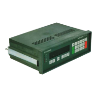
Cable Fastening
In the rear wall of the INTECONT, under each
connector, several slots are provided. The
upper slot pair is reserved for the cable clamp
which presses the shielded cable against the
rear wall. The shield needs not be separately
connected. The lower cut-out serves for
accommodation of a pull relief, e.g. by cable
binders.
Attention!
Connectors to base card require to be plugged-in
with screwed connections up; connectors to option
card, with screwed connections down.
n
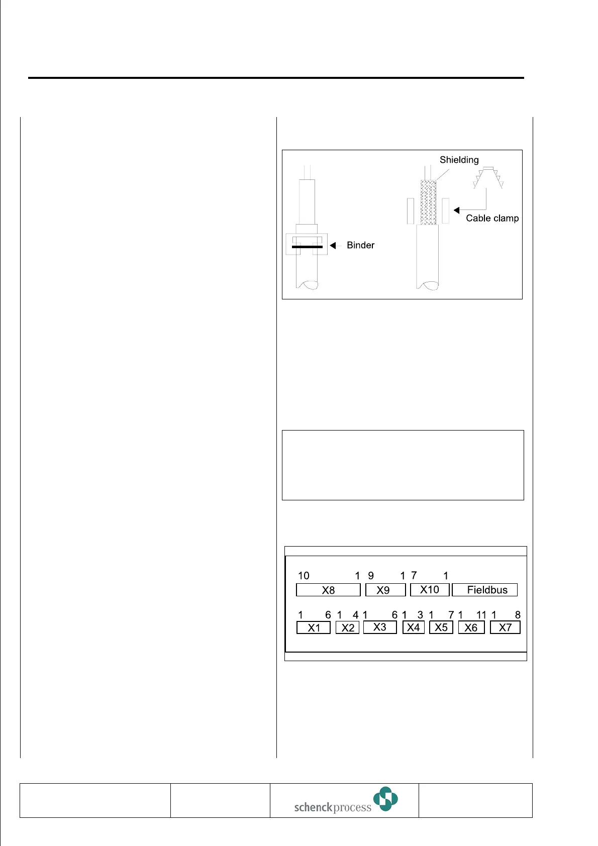
Intecont rear view: Connectors
0837
VBW INTECONT PLUS
Details
BV-H2214 GB 106
Technische
Redaktion PDE-RD
Transmission to third parties and reproduction of
this documentation are not permitted. Schenck
Process GmbH reserves all rights of ownership
and copyrights.
 Loading...