15.6 DeviceNet module (VCB8020)
The module may be attached to the main board of the INTECONT® Satus to create an
interface between the CAN bus and the DeviceNet procedure.
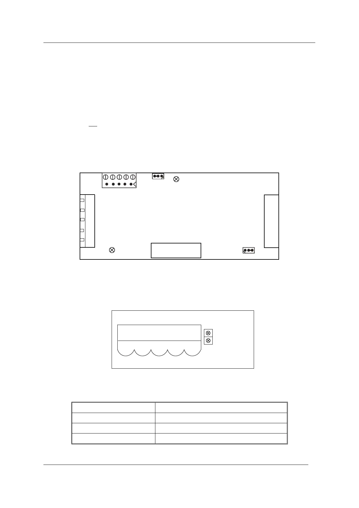
Bus termination
n
The bus termination resistances must be activated at the first and last station of the bus.
This is done by applying the W160 jumper to the position 1-2. By default, the resistances
are not
activated (position 2-3).
Baud rate and bus addresses:
n
Both values are set using parameters.
The W100 jumper, for determining the power supply, must be plugged in position 2-3.
Network Status (LED)
Status Indication
Off Not online/ No power
Green Online, one or more connections are established
Flashing Green (1Hz) Online, no connections established
76 BV-H2346GB / 0833 Operating Manual INTECONT® Satus
© Schenck Process
DeviceNet 15.6 DeviceNet module (VCB8020)
vh233407.cdr
XP3
DC/DC
H110
H120
VCB8020
XP1
5 4 321
1
Feldbuskarten-
Verbinder
W100
1
2
3
4
5
W160
1
1
2
3
4
5
XP1
Module Status LED
Network Status LED
Front View