Safety and Functional Tester GLP2-i/e
During the test, test object and test leads must not be touched!
The safety measures required by law must be adhered to!
Schleich GmbH * D-58675 Hemer * 0049 / (0)2372 / 9498-0 * 0049 / (0)2372 / 9498-99 *
http://www.schleich.com * info@schleich.com 75
The picture shows a resistance Rx and 2 test probes. The test probes have 2 contact pins each, which are
insulated against each other. Therefore there are 4 contact points altogether at the resistance to be
measured.
At the 4-wire measurement (also called Kelvin measurement), the contact resistance at the contact point
between test probe and test object is compensated. This takes place, because the contact pin touches the
test object with 2 separate contacts.
One contact supplies the current into the test object and the 2
nd
contact serves for detecting the voltage
drop at the test object. Since the contact resistance is “behind” picking off the voltage drop, it is not
relevant for measuring the voltage drop. For measuring the voltage drop, a high-ohmic voltage measuring
device is necessary. The contact resistance at the 2
nd
contact point in comparison to the resistance of the
voltage meter is thus, as a percentage, completely irrelevant.
This method is always used for measuring very small resistances. This especially applies to the PE test or to
measuring low-ohmic winding resistances.
If contacting the test object in 4-wire technique is too complicated, it would still make sense to have the
supply leads up to the test object in 4-wire technique. The measure result would therefore be independent
from the length of the test lead and from unidentifiable contact resistances in the tester (e.g. relays).
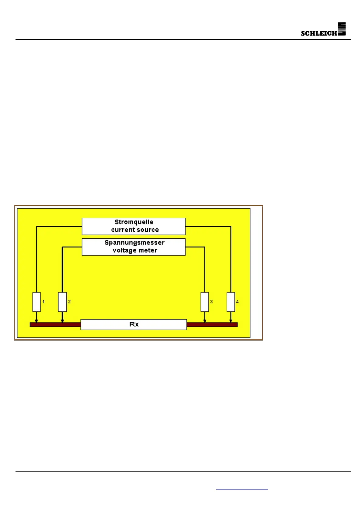
The picture shows the schematics of the individual resistances of the equivalent circuit. Resistances 1 and 4
are the resistances at the contact points of the current connections. Resistances 2 and 3 are the contact
resistances in the voltage measuring circuit. You can see clearly that for the voltage drop test at the
resistance Rx the resistances 1 and 4 are no longer relevant. As described above, in order to avoid measure
errors, the internal resistance of the voltage meter must be very high in comparison to the resistances 2
and 3. In praxis this is the case, because 2 and 3 are mostly below 1 Ohm. The internal resistance of the
voltage meter is normally higher than 1MOhm.