SEA SYSTEMS
INSTALLATION AND USE MANUAL
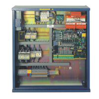
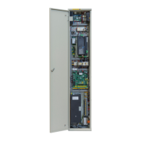
CONTROL PANEL and PREWIRED SYSTEM STK1
For Electric and Hydraulic Lifts
MSTK12-GB
Rev.01
30/12/05
SETRONIK1 Pagina 22 di 54
A) F
IXING AND CONNECTION OF THE STOP SENSORS AT THE FLOORS:
7. Fix on the roof car the IS and ID sensors and at every floor on the guide the magnet
couples so that, with the car at the landing floor, both sensors and magnets are
perfectly aligned according to the diagram CVIA (with A system or B system) or the
diagram CVIC (with C system);
8. Connect IS, ID sensors as per the installation diagrams;
9. Adjust the pairs of magnets so that, going up and down, the car stops with the floor
aligned at the landing floor.
B) FIXING OF SPEED-CHANGE SENSORS:
10. Fix next at every floor on the guide the round magnet couples, so that they are
aligned to the sensors IS and ID according to the diagram CVFA;
11. Fix on the car roof the sensors SR and DR and next to the upper floor and the lower
floor on the guide the round magnets so that the sensors and magnets are aligned
as specified in the layout L02;
12. Connect SR, DR sensors according to the installation diagrams;
13. Adjust the pairs of magnets to match slowing distance K from the landing as per the
table attached to diagram CVFA.
WARNING
To make sure that sensors switch over properly, ascertain that:
• The distance between contiguous magnets on the same axis is major than 5
cm;
• the sensor and its corresponding magnet are kept 1÷1.5 cm apart