SEA SYSTEMS
INSTALLATION AND USE MANUAL
CONTROL PANEL and PREWIRED SYSTEM STK1
For Electric and Hydraulic Lifts
MSTK12-GB
Rev.01
30/12/05
SETRONIK1 Pagina 11 di 54
2.6.FIXING AND CONNECTION IN THE SHAFT
2.6.1.SHAFT LINE
1. The shaft line is formed by a taped coil of single-pole, colour-coded and numbered
wires, including plugged-in connectors with labels to the control panel side.
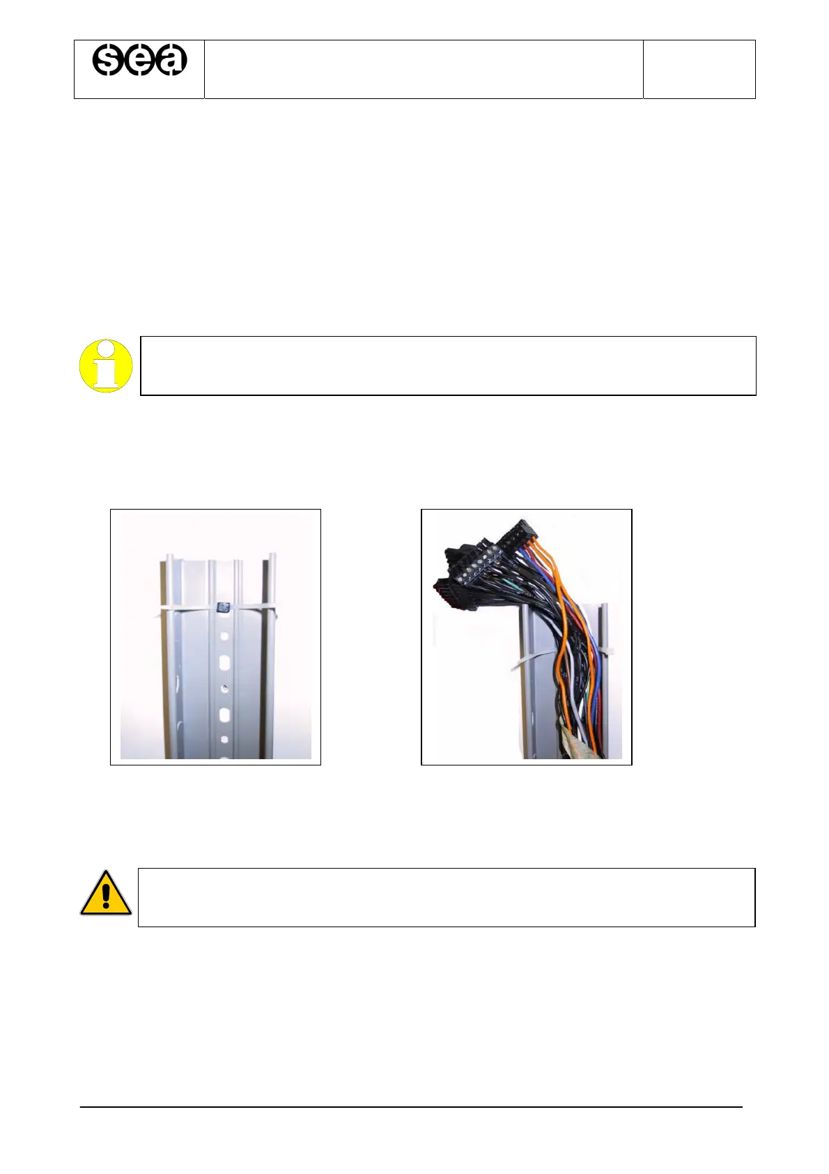
2. Fasten the wireway (P/N P-00060) with appropriate plugs (P/N P-00075) next to the
landing push-button panels, making sure to keep a maximum distance of 1 m from
the doors. If a dual-operator lift has been installed, fit the wireway closer to the most
widely used side
HIGHLIGHT
Set the plug with the clamp (P/N P-00074) already inserted into the eyebolt
before securing it (Fig. 2.2);
3. Temporarily secure the coil on top of the shaft and lower it into the shaft from the
top, letting the side fitted with plugged-in connectors in, to the control panel (Fig.
2.3);
Fig. 2.2. Fig. 2.3
4. Connect the frame connectors to the control panel as per installation diagrams
5. Lay down the coil, starting from the control panel section, using clamps to rivet it to
the retaining plugs of the wireway, all the way to the upper end of the shaft;
WARNING
If cable quantity is too large on the upper side, cut the wires and insulate them
with electric tape or use the previously removed connectors.