SEA SYSTEMS
INSTALLATION AND USE MANUAL
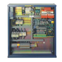
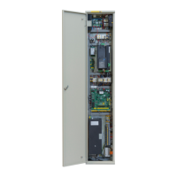
CONTROL PANEL and PREWIRED SYSTEM STK1
For Electric and Hydraulic Lifts
MSTK12-GB
Rev.01
30/12/05
SETRONIK1 Pagina 25 di 54
3.PROGRAMMING
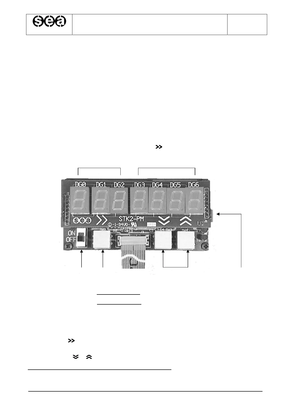
3.1PROGRAMMER CONNECTION (STK2-PM)
1. Check that the ON\OFF switch of the Keyboard is in the OFF position.
2. Insert the connection cable in connector FC3 on the STK1-B board.
3. Bring the ON\OFF switch in the ON position.
4. All the 7 displays show the number 8 for about 2”: this function is used to check that
all displays are working correctly.
5. After the 2”, the displays show 0.00.XXXX (X indicates any number), or 0.00.0000
with the last four digits flashing. In this second case it means that an access code
has been stored and that it is therefore necessary to enter the digits of the access
code in the last 4 displays (DG3..DG6) and then to press .
ab
d e f g c
a= Displays indicating the Parameter Code, marked as DG0, DG1 and DG2.
b= Displays indicating the Parameter Value, marked DG3, DG4, DG5, DG6.
c= DIN guide release
d= ON\OFF switch.
e= Connection cable to connector FC3 on the STK1-B board.
f= Pushbutton to select the display from DG0 to DG6, scrolling from left to right
whenever it is pressed. The selected display flashes.
g= Pushbuttons , to modify the number of the display previously selected.
(Please refer to ‘Example of programmer use’ Par. 3.2)