SEA SYSTEMS
INSTALLATION AND USE MANUAL
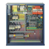
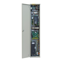
CONTROL PANEL and PREWIRED SYSTEM STK1
For Electric and Hydraulic Lifts
MSTK12-GB
Rev.01
30/12/05
SETRONIK1 Pagina 50 di 54
5.MAINTENANCE
Before carrying out any cleaning or maintenance operations, unplug the appliance from
the power supply unit by turning OFF the master switch.
While maintenance procedures are in progress, refer to the safety regulations set out in
paragraph 2.
In no event shall SEA SYSTEMS Srl be liable for any damages whatsoever arising out of
the inability to comply with the above instructions and of any improvements as regards
configuration, fastening and connections in the originally supplied apparatus.
5.1.BATTERY REPLACEMENT
The control panel is fitted with the following batteries:
• 12v 2Ah. or
• 12v 7.5Ahif an emergency descent is provided for
The battery lasts approximately 3 years provided it remains charged.
Check out its condition on a yearly basis and replace it with one featuring the same
characteristics if needed.
5.2.SHAFT SENSORS
Shaft indicators are formed by monostable and/or bistable sensors and their
corresponding magnets to enable switching.
In order to ensure that sensors switch over properly when placed opposite their
corresponding magnets, check out on a yearly basis
that:
- The distance between the sensor and its corresponding magnet is kept 1 cm apart,
including during machining stress;
- Sensors travel the same axis as the magnets;
- Magnets have no metal bodies attached;
- The brackets for both the sensors and magnets are steadily fastened to the car roof
and the guides.