SEA SYSTEMS
INSTALLATION AND USE MANUAL
CONTROL PANEL and PREWIRED SYSTEM STK1
For Electric and Hydraulic Lifts
MSTK12-GB
Rev.01
30/12/05
SETRONIK1 Pagina 12 di 54
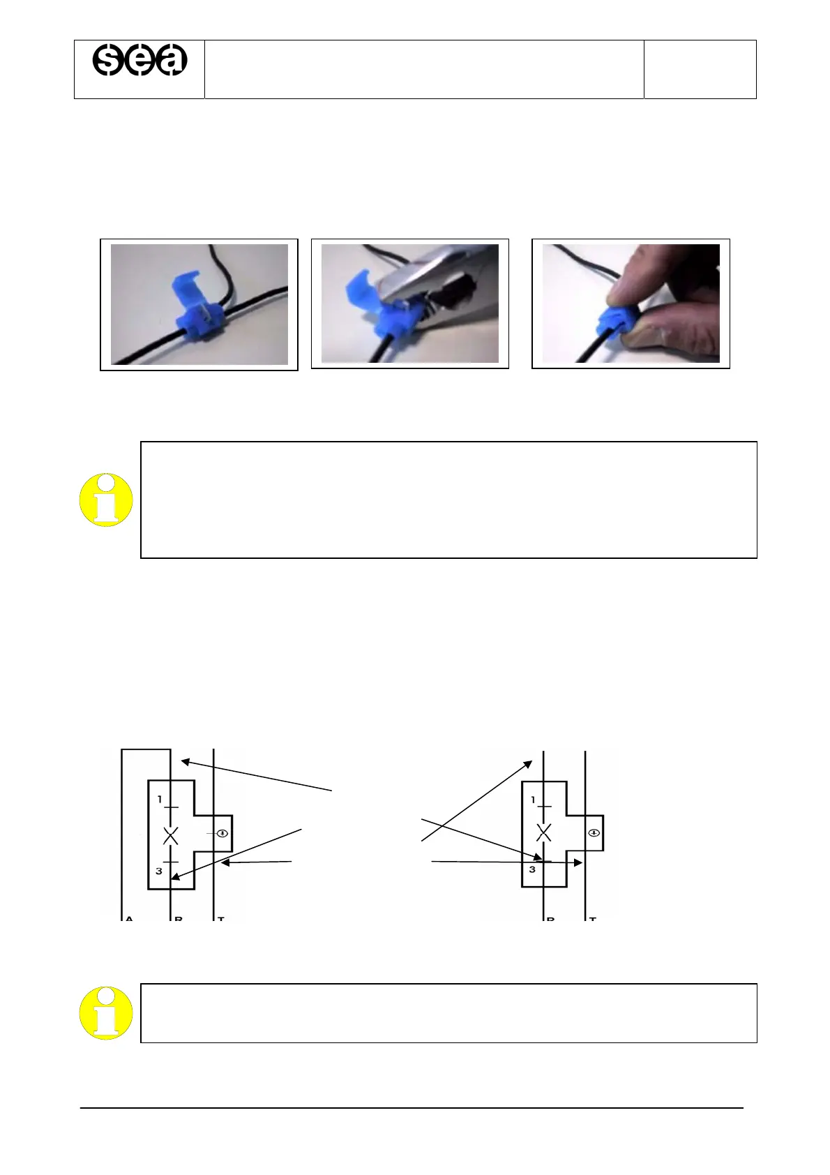
2.6.2.C
ONNECTIONS WITH BRANCH POINT TO THE SHAFT LINE
Use red and blu connectors (Cod. P-00084, P-00085) following the operations in figure 2.4
for the connections with branch point to the shaft line (see installation diagrams).
Fig. 2.4 –Sequence of operations for the connection with branch point
HIGHLIGHT
Generally the devices that need a connection with branch points are:
- Run limit switch;
- Floor push buttons;
- Alarm siren;
- Stop in the pit
2.6.3.CONNECTIONS IN SERIES TO THE SHAFT LINE
Use orange connectors (BC1 and BC2) following the operations in figure 2.7 for the
connections in series to the shaft line (see installation diagrams).
Connect the last device of the series according to the figure 2.5, and the first devices of
the series according to the figure 2.6
Fig. 6.4.3Fig. 6.4.4
Upper End Landing ConnectorIntermediate Landings Connectors
Fig. 2.5 Fig. 2.6
Last connection in the series First connections in the series
HIGHLIGHT
Generally the devices that need a connection in series are:
- Safety contacts for floor door lockings
WIRE COLOURS:
PINK
ORANGE
YELLOW / GREEN