Operator control
8.3 Special displays
SENTRON PAC4200
System Manual, 09/2009, A5E02316180B-02
133
8.3 Special displays
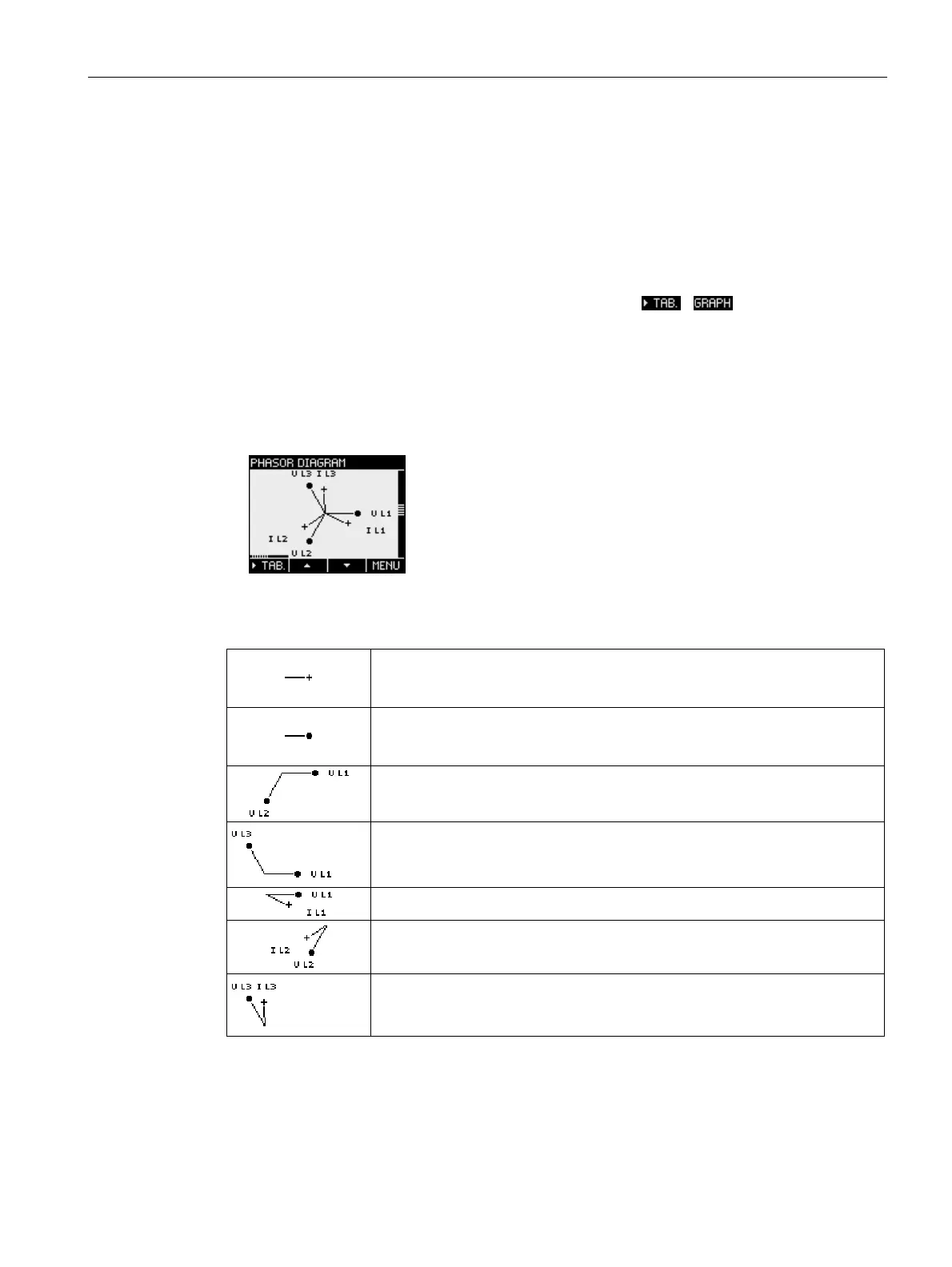
8.3.1 Phasor diagram
The phasor diagram provides a coherent picture of the actual unbalance values of the
fundamental.
The graphical representation is assigned a value table. F1
/ switches between
the two representations.
Graphical representation
● Phase angle and displacement angle
● Amplitude unbalance, expressed as the length of the axes on the graph.
Figure 8-14 Phasor diagram
Table 8- 5 Symbols used in the phasor diagram
Current
Voltage
Phase angle a-b
Phase angle a-c
Displacement angle a
Displacement angle b
Displacement angle c