Doc# E166703 5-6
5: Communicating with the Meter
Electro Industries/GaugeTech
The Leader In Power Monitoring and Smart Grid Solutions
Electro Industries/GaugeTech
The Leader In Power Monitoring and Smart Grid Solutions
Electro Industries/GaugeTech
The Leader In Power Monitoring and Smart Grid Solutions
The Unicom 2500 can be configured for either 4-
wire or 2-wire RS485 connections. Since the
MP200 unit uses a 2-wire connection, unless
you are using the RS485 4-wire to 2-wire
communication cable available from EIG’s
online store, you will need to add jumper wires
to convert the Unicom 2500 to the 2-wire config-
uration. As shown in Figure 5.6, you connect the
"RX-" and "TX-" terminals with a jumper wire to
make the "-" terminal, and connect the "RX+"
and "TX+" terminals with a jumper wire to make
the "+" terminal. See the figure on the right for
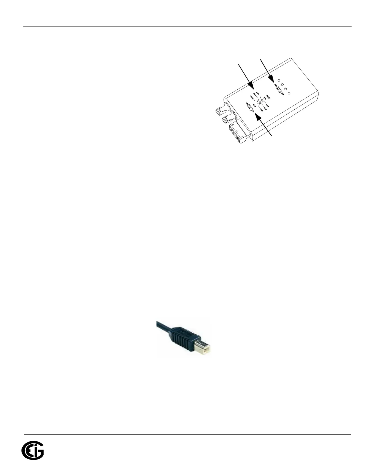
Figure 5.7: Unicom 2500 Settings
the Unicom 2500’s settings. The Unicom’s baud rate must match the baud rate of the
MP200 unit’s RS485 port: you set the baud rate by turning the screw to point at the
rate you want.
5.1.3: USB Port (Com 2)
The MP200 unit’s Com 2 USB port allows it to communicate with a computer that has
a USB 1.1 or USB 2.0 Host port. The MP200 unit's USB port is configured to operate
as a virtual serial communication channel that the PC sees as a simple COM port. The
USB virtual serial communication channel:
• Is compatible with standard USB cables that terminate with a USB Type B plug (see
Figure 5.8)
• The maximum length of the USB cable is 5 meters. Greater lengths require hubs or
active extension cables (active repeaters).
Figure 5.8: USB Type B Plug
If you are using a PC with the Windows® 7 (or later) Operating System, connect the
USB cable from your PC to the unit’s USB port on the front panel. The Windows® 7
Operating System will install a driver for you. For earlier operating systems, EIG pro-
vides a driver for PC compatible computers. The driver configures the computer's USB
Set switch
to DCE
Set the
baud rate
Set switch
to HD