Operating Instructions Chapter 10
C4000 Micro/Basic/Basic Plus/Eco
8009423/YT79/2016-03-14 © SICK AG • Industrial Safety Systems • Germany • All rights reserved 47
Subject to change without notice
Technical specifications
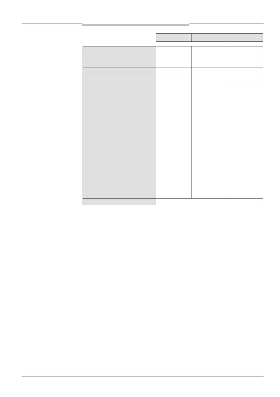
Minimum Typical Maximum
Permissible cable resistance
Between device and load
11)
2.5 Ω
Supply lead
1 Ω
Power consumption 0.45 A + max.
1 A OSSD load
External device monitoring (EDM)
input
Input voltage
12)
HIGH (inactive) 11 V 24 V 30 V
Input current HIGH 6 mA 10 mA 20 mA
Input voltage
12)
LOW (active) –30 V 0 V 5 V
Input current LOW –2.5 mA 0 mA 0.5 mA
Contactors
Permissible dropout time
300 ms
Permissible pick-up time
300 ms
Control switch input
(reset button)
Input voltage
12)
HIGH (active) 11 V 24 V 30 V
Input current HIGH 6 mA 10 mA 20 mA
Input voltage
12)
LOW (inactive) –30 V 0 V 5 V
Input current LOW –2.5 mA 0 mA 0.5 mA
Operation time control switch
input
110 ms
Weight Depending on protective field height (see page 50)
11)
Make sure to limit the individual cable resistance to the downstream controller to this value to ensure that a
cross-circuit between the outputs is safely detected. (Also note EN 60 204 Electrical Machine Equipment,
Part 1: General Requirements.)
12)
As per IEC 61 131-2.