36 DUSTHUNTER T · Operating Instructions · 8012428 V 2.0 · © SICK MAIHAK GmbH Germany
Assembly and Installation
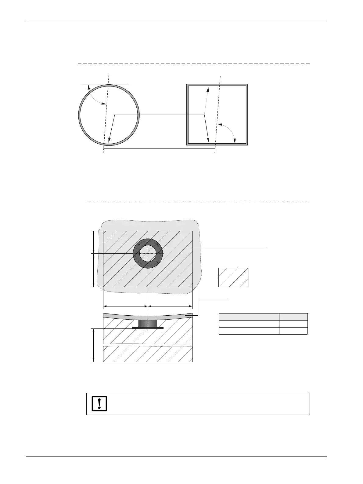
At ducts with strongly reflective material we recommend to define the measurement axis
according to the following figure to prevent possible measurement influences by disturbing
reflections.
Bild 17 Measurement axis at strongly reflective duct walls
Work to be performed
b
Measure the fitting location and mark the assembly location.
Leave enough clearance around the flange with tube to fit the sender/receiver unit and
reflector (
→
Fig. 18).
Figure 18 Clearance for sender/receiver unit and reflector (dimensions in mm)
b
Remove insulation (when fitted)
b
Cut suitable openings in the duct wall; bore large enough holes in brick or concrete
stacks(flange tube diameter (
→
p. 115, Fig. 89))
b
Insert the flange with tube in the opening so that the "Top" marking points upwards
(
→
p. 35, Fig. 16).
Strongly
reflective
duct wall
Measurement
axis
< 90 °
< 90 °
TOP
Flange with tube
Clearance
a400
600 300 200
Component a
Sender/receiver unit 400 mm
Reflector 350 mm
Duct wall
NOTICE:
Do not let separated pieces fall into the duct.

 Loading...


