Operating Instructions GM35
Probe Model
Maintenance
8009389/07-2006 © SICK MAIHAK GmbH • Germany · All rights reserved 69
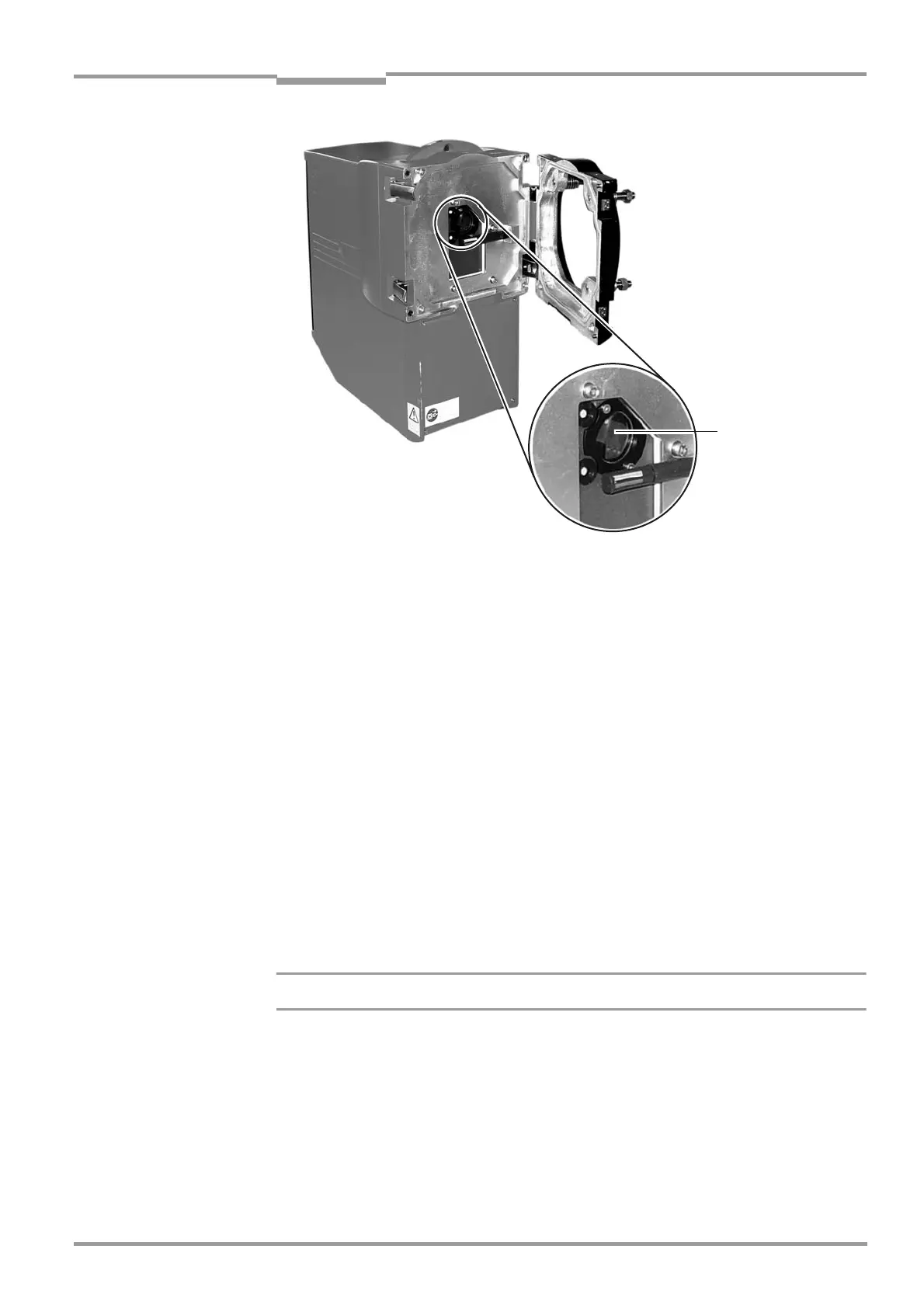
Fig. 37 Optical boundary surface
8.3 Maintenance activities on the purge-air unit
Only if purge air
is used
This Chapter only applies to GM35 configurations with purge-air supply, that is, those using
a GMP measuring probe. The reliability of the purge-air system is essential for ensuring the
availability of the measuring system. Maintenance of the purge-air supply is straightforward,
but should be carried out extremely carefully.
Prerequisites for maintaining the purge-air supply:
– The measuring probe with the SR unit is located outside the measurement gas duct; if
the duct contains a partial vacuum that is sufficient to flush it adequately with ambient air
when the purge-air supply is removed, the probe can remain inside the duct while the
purge-air unit is being maintained.
– The SR unit has been opened fully on the flange attachment so that any dust blown
through the purge-air hose during maintenance is not deposited on the optical boundary
surfaces of the SR unit and measuring probe. As described below, the purge-air hose
should be disconnected from the measuring probe while maintenance is being carried
out.
8.3.1 Preparation and general inspection
Never switch off the purge-air unit while the measuring probe is in the duct!
‡ With the purge-air unit switched on, remove the purge-air hose from the purge-air inlet on
the measuring probe or optional differential pressure monitor to prevent any dust that
has been released during maintenance from being deposited on the optical boundary
surfaces of the measuring probe and SR unit.
‡ Switch off the power supply (three phase) to the purge-air unit and, if necessary, attach
a visible warning to prevent it from being reconnected inadvertently while maintenance is
being carried out.
Optical boundary
surface (front window

 Loading...


