Repairs
FLOWSIC600-XT · Service Manual · 8019179/V0-2/2016-03 · © SICK Engineering GmbH 43
Subject to change without notice
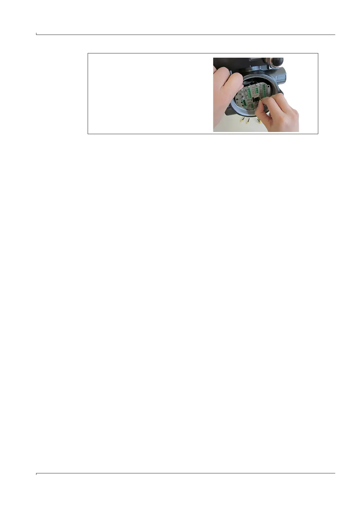
3 Pull the I/O block out with the tab
provided.
– Take care not to damage the
cable gland in the Ex-e terminal
compartment.
– Carefully push the cables
upwards and move the I/O block
past the cables.