Operating Instructions
LMS500 Product Family
Product description
8013796/UL20/2010-09-27 © SICK AG · Division Auto Ident · Germany · Subject to change without notice 17
Chapter 3
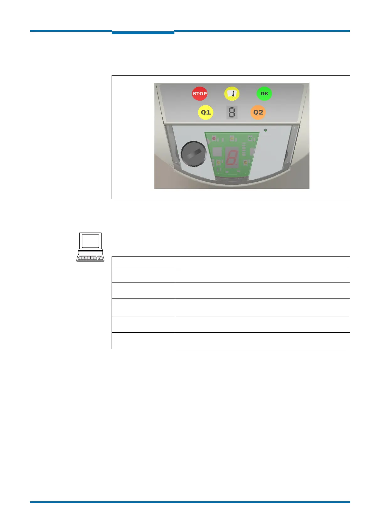
3.4.2 Status indicators
The LEDs and the 7Fsegment display indicate the operational status of the LMS.
Fig. 2: Status indicators
Important • On the LMS, along with the standard displays described below, the indication functions
of the LEDs and the 7Fsegment display can be configured in SOPAS ET.
PROJECT TREE, LMS…, PARAMETER, NETWORK/INTERFACES/IOS, DISPLAY.
LEDs
Further information see section 8.2 “Error displays of the LEDs” on page 65.
7?segment display
Used for diagnostics on occurring errors or malfunctions (see section 8.3 “Indications of the
7-segment display” on page 66).
Display Possible cause
LMS in operation, no evaluation field is signalling an event
LMS in operation, at least one evaluation field is signalling an event
front screen contaminated
Switching output OUT1 switched (see section 3.8.3 “Operator for the
evaluation cases on the output” on page 33)
Switching output OUT2 switched (see section 3.8.3 “Operator for the
evaluation cases on the output” on page 33)
Tab. 6: Meaning of the LEDs

 Loading...


