Mounting
42 © SICK AG · Division Auto Ident · Germany · Subject to change without notice 8013796/UL20/2010-09-27
Operating Instructions
Laser Measurement Systems of the LMS500 Product Family
Chapter 4
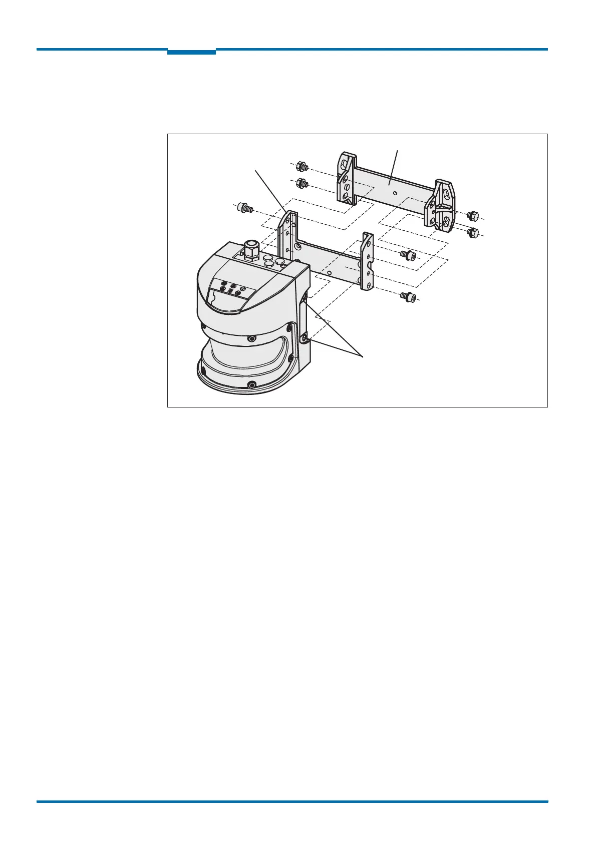
4.3.3 Mounting with mounting kit 2
With the aid of mounting kits 2 (only in conjunction with mounting kit 1) you can align the
LMS in two planes. The maximum adjustment angle is ±11° in both planes.
Fig. 24: Mounting with mounting kit 2 and 3
1. Mount the mounting kit 2 on the mounting surface.
2. Then mount mounting kit 1 on mounting kit 2.
3. Then mount the LMS on mounting kit 1.
4. Adjust the LMS longitudinally and cross-wise.
Important During mounting, please observe the dimensional drawings (see section 9.2.3
“Dimensional drawings, mounting kits” on page 72).
Fixing screws
Mounting kit 1
Mounting kit 2
Threaded holes M8×9
 Loading...


